
Microwave hyperspectral receiver and method

A hyperspectral and receiver technology, applied to electrical components, transmission systems, etc., can solve problems such as increased system complexity, increased scanning time, and adverse weather changes, achieving the effect of reducing scanning time and reducing complexity

Inactive Publication Date: 2012-12-26
BEIJING KUNQI ELECTRONICS SYST
View PDF6 Cites 15 Cited by
  • Summary
  • Abstract
  • Description
  • Claims
  • Application Information

AI Technical Summary

Problems solved by technology

If the superheterodyne receiver structure is selected, the received signal is down-converted to zero intermediate frequency by down-conversion, and then a fixed low-pass filter is used to filter the required bandwidth. The selection of the frequency band depends on the signal transmitted by the frequency synthesizer Frequency, because the frequency synthesizer can only transmit one signal frequency at the same time, so this frequency band division method needs to complete the down-conversion process in time order, which leads to the increase of system scanning time, which is not conducive to the observation of rapid weather changes ; If the receiver array structure is selected, the receiver array divides the power of the received signal into multiple channels, and then uses multiple band-pass filter banks to filter the required frequency bands. The selection of frequency bands depends on the frequency response of the band-pass filter banks. The signal power is divided into multiple band-pass filter banks to work at the same time, so this frequency band division method is a process of completing the frequency band division in parallel. However, the number of band-pass filter banks is equal to the number of channels of the receiver, so the number of receiver channels is large At the same time, the complexity of the system also increases, which is not conducive to the development and delivery of microwave radiometers.

Method used


Image

  • Microwave hyperspectral receiver and method
  • Microwave hyperspectral receiver and method
  • Microwave hyperspectral receiver and method

Examples


Embodiment Construction

[0063] The technical solutions in the embodiments of the present invention will be clearly and completely described below in conjunction with the accompanying drawings in the embodiments of the present invention. Obviously, the described embodiments are only some, not all, embodiments of the present invention. Based on the embodiments of the present invention, all other embodiments obtained by persons of ordinary skill in the art without creative efforts fall within the protection scope of the present invention.

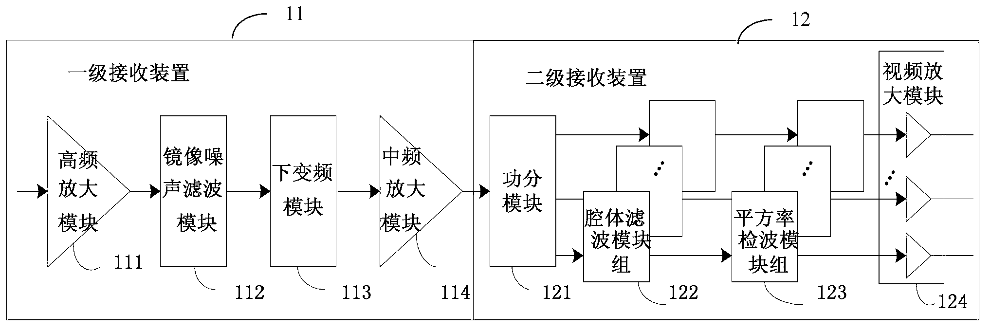
[0064] see figure 1 , is a schematic structural diagram of a microwave hyperspectral receiver provided by an embodiment of the present invention, the device includes: a primary receiving device 11 and a secondary receiving device 12, wherein,

[0065] The primary receiving device 11 is used to receive the high-frequency signal input by the antenna, divide the high-frequency signal into frequency bands, and down-convert the high-frequency signal divided into frequency...


PUM


Abstract

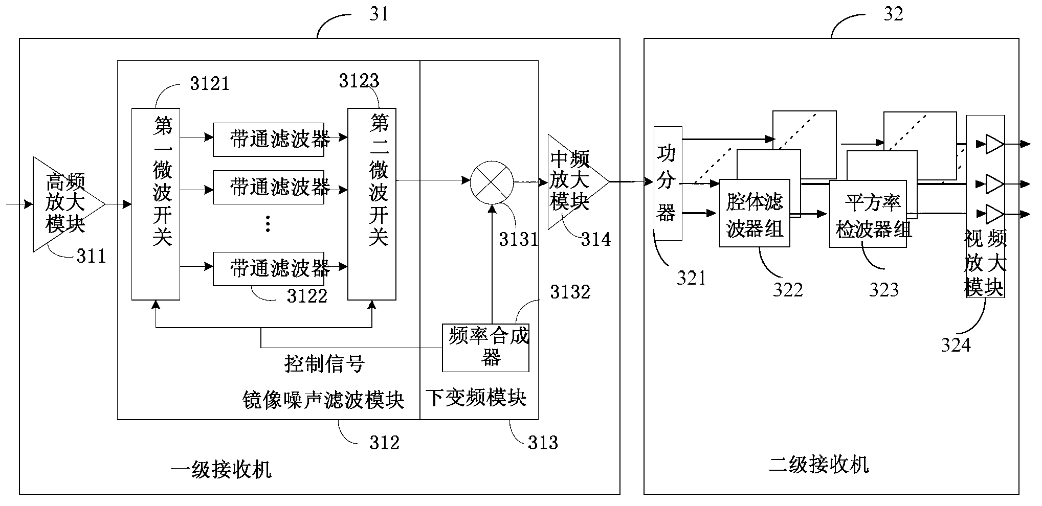
The invention provides a microwave hyperspectral receiver and a method. The microwave hyperspectral receiver comprises a primary receiving device and a secondary receiving device, wherein the primary receiving device is used for receiving high-frequency signals input by an antenna, carrying out frequency band division on the high-frequency signals, carrying out down-conversion on the high-frequency signals subjected to frequency band division to form first intermediate-frequency signals and amplifying and outputting the first intermediate-frequency signals to the second receiving device; and the second receiving device is used for receiving the amplified first intermediate-frequency signals, carrying out equipower division on the first intermediate-frequency signals to form multiple intermediate-frequency signals, carrying out frequency band division and square rate detection in sequence on each path of intermediate-frequency signals in the multiple intermediate-frequency signals to obtain voltage signals with sky brightness temperature information and amplifying and outputting the voltage signals. According to the invention, two stages of receiving units which are of a cascaded structure are adopted, and the frequency band division of the first receiving device is implemented serially according to the time sequence, therefore the system complexity is reduced; and the frequency band division of the second receiving device is implemented in parallel, therefore the system scanning time is shortened.

Description

technical field [0001] The invention relates to the field of meteorological monitoring, in particular to a microwave hyperspectral receiver and method. Background technique [0002] In terms of meteorological monitoring, traditional multi-channel microwave radiometers use two receiver structures: superheterodyne receiver and receiver array. The superheterodyne receiver down-converts the high-frequency signal output by the antenna to low-frequency processing, and divides the frequency band by tuning the local oscillator frequency; the receiver array directly performs power division and filtering processing on the antenna output signal to complete the frequency band division. The microwave hyperspectral radiometer needs to obtain continuous atmospheric radiation spectral lines in the working frequency band, and the number of channels of the receiver reaches more than one hundred. If the superheterodyne receiver structure is selected, the received signal is down-converted to z...

Claims


Application Information

Patent Timeline
IPC IPC(8): H04B1/16
Inventor 谢衍苗俊刚黄干明钱太阳
Owner BEIJING KUNQI ELECTRONICS SYST
Learn More