Brake retaining device of electric sweeper

A technology for holding devices and mechanisms, applied to manual sweeping machines, machine parts, etc., can solve problems such as mismatching of sweeping machines, poor timeliness of operation, poor coordination, etc., and achieve good parking stability, good timeliness, and lock bit easy effect

Inactive Publication Date: 2013-01-02
江苏路驰洁环保车业有限公司
View PDF14 Cites 0 Cited by
  • Summary
  • Abstract
  • Description
  • Claims
  • Application Information

AI Technical Summary

Problems solved by technology

Although the parking structure of the prior art is simple and the brakes are reliable, each operation re...

Method used


Image

  • Brake retaining device of electric sweeper
  • Brake retaining device of electric sweeper
  • Brake retaining device of electric sweeper

Examples


Embodiment Construction

[0016] The present invention will be further described below according to accompanying drawing.

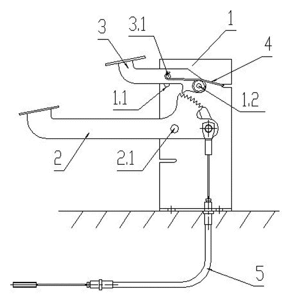
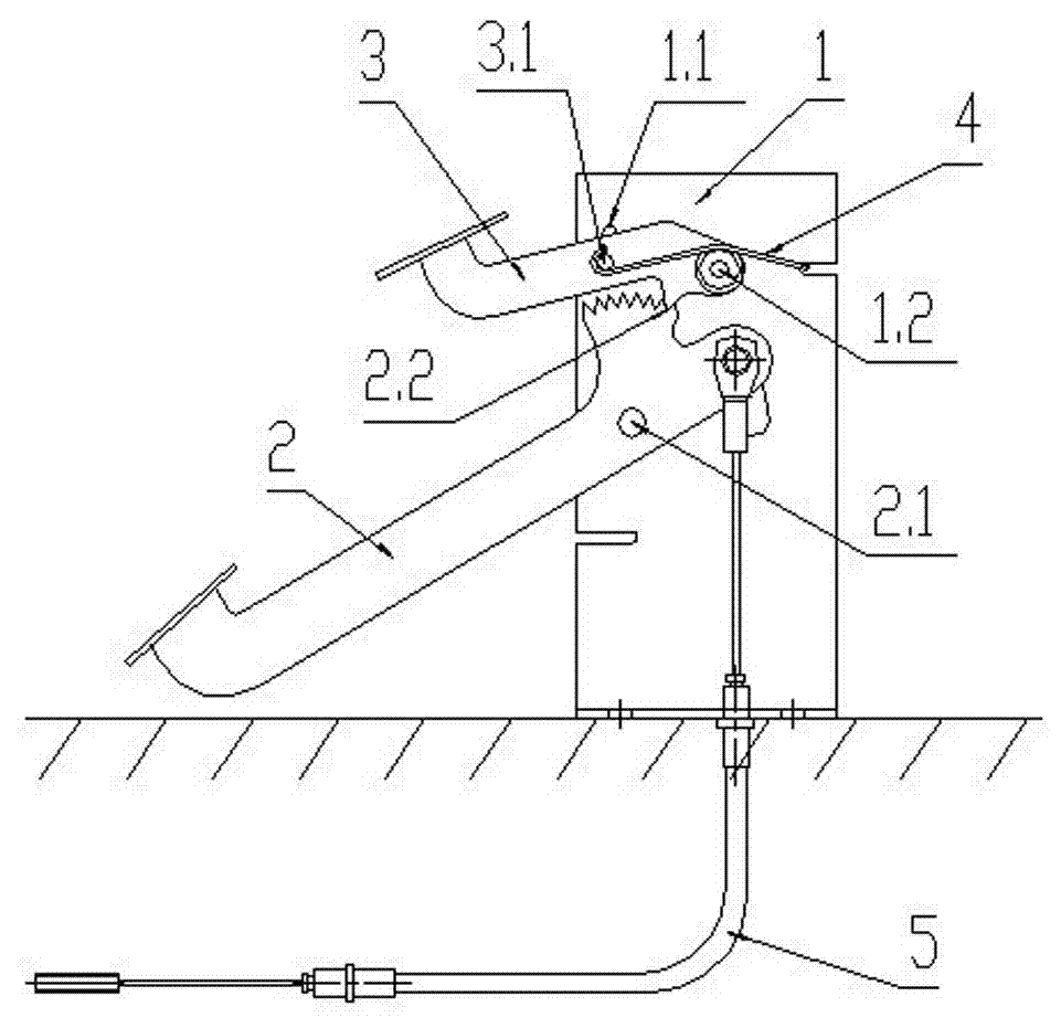
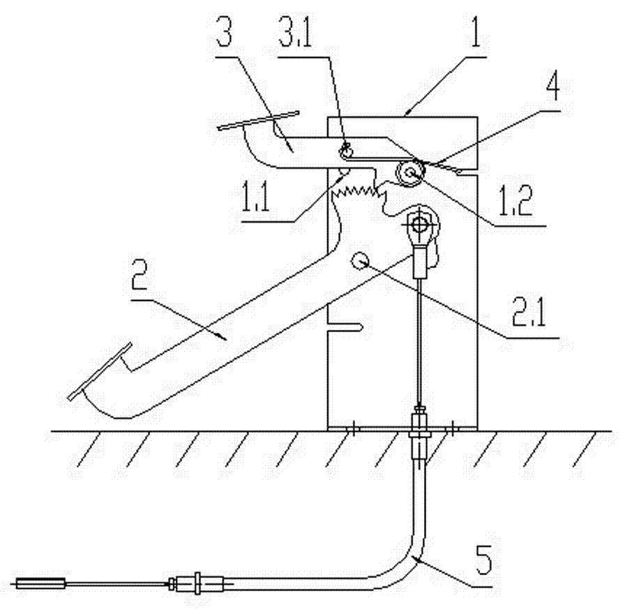
[0017] figure 1 The shown electric vehicle sweeper brake holding device includes a bracket 1 , a long pedal 2 , a short pedal 3 , a spring 4 and a drag cable 5 . The support 1 is a double-layer vertical rectangular frame, and the inserted long pedal rod 2 is hinged between two layers of parallel and alternate board surfaces through a pin 2.1, and the right end of the long pedal is hinged with the drag cable 5 at the bottom of the support 1. A lever-type brake mechanism that controls the action of the dragline with the pin 2.1 as the fulcrum is formed. Long step bar 2 right-hand upper flange among the present invention is provided with fan-shaped ratchet, and the circle center of fan-shaped ratchet is positioned at the hole center of positioning installation pin 2.1 on long step bar 2. The right end of the short pedal 3 is provided with two through holes, the short pedal 3 is ins...


PUM


Abstract

The invention discloses a brake retaining device of an electric sweeper, which comprises a bracket, a long foot bar, a short foot bar, a spring and an inhaul cable. A right end of the long foot bar is connected with the inhaul cable, and the long foot bar is hinged with the bracket through a pin to form a lever type brake mechanism. The short foot bar is installed on the long foot bar through a mandrel and a hinge pin, the downside of the short foot bar is provided with a ratchet to mesh with a fan-shaped ratchet wheel raised on the long foot bar; and the short foot bar of a cantilever keeps the position under the action of the inhaul cable and locks the long foot bar, therefore the purpose of parking after brake is realized. The integrative installing structure of the long foot bar and the short foot bar is located in the same one foot control scale, when the long foot bar is stepped to carry out the brake, the short foot bar also can be stepped; the brake retaining device is convenient to operate, good in timeliness, likely to lock, and stable and reliable in parking. The invention is applicable to be matched with various sized sweepers as well as ordinary locomotives.

Description

technical field [0001] The invention relates to a mechanical limit structure, in particular, the invention relates to a braking and holding device for an electric sweeper. Background technique [0002] During the operation of the electric sweeper, it is common for the staff to make temporary parking according to the road conditions. Under normal circumstances, the brakes are first applied before the temporary parking, and then the parking operation is performed. The parking device is a special mechanical limit structure to keep the vehicle in the braking state, so as to avoid the accident of losing control of the vehicle after the staff get off the vehicle. The parking device and the brake device of the existing commodity electric sweeper configuration on the market are separated into two places and operated separately. Although the parking structure of the prior art is simple and the brakes are reliable, each operation requires both hands and feet, poor timeliness of opera...

Claims


Application Information

Patent Timeline
IPC IPC(8): A47L11/24A47L11/40
Inventor 缪平
Owner 江苏路驰洁环保车业有限公司
Why Eureka
Try Eureka