Dual-core concurrent universal swing mechanism

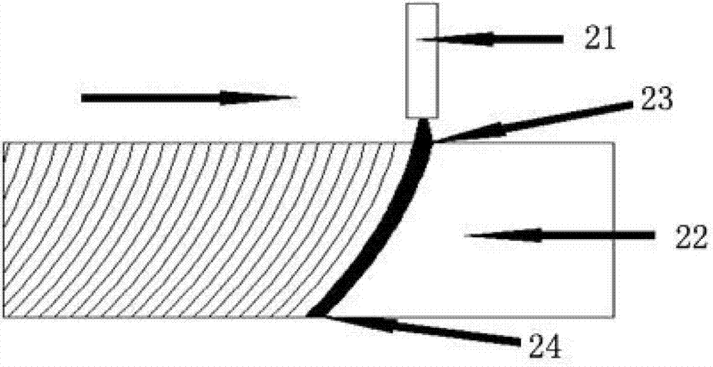
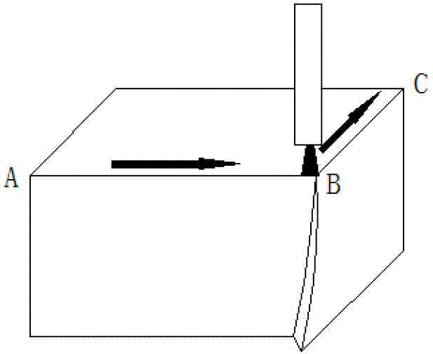
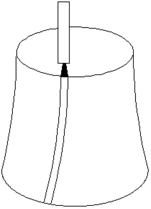
A common point and swing technology, which is applied in the field of double-center common point universal swing mechanism, can solve problems such as complex design, pipeline and cable winding, and shape error at small arcs, so as to avoid winding problems and increase process flexible effect

Active Publication Date: 2015-04-15
柔锋机械科技(江苏)有限公司
View PDF7 Cites 0 Cited by
  • Summary
  • Abstract
  • Description
  • Claims
  • Application Information

AI Technical Summary

Problems solved by technology

[0003] Defect 1: When the cutting direction needs to be changed when cutting to the corner, due to the lag of the stream injection point, the stream cannot be turned up and down synchronously, resulting in shape errors at the corner (such as figure 2 )
[0004] Defect 2: When cutting an arc, the cutting direction needs to be changed at any time. Due to the lag of the jet exit point, the up and down streams cannot be turned synchronously, resulting in shape errors at small arcs (such as image 3 )
[0005] Defect 3: When the flow beam interacts with the material, at the upper part of the material to be cut near the injection point, due to the high energy of the flow beam, the material can be quickly cut off, but as the cutting depth increases, the energy of the flow beam gradually decays, Decreased cutting ability
Disadvantage: the vertical axis of rotation can cause tangled problems in the tubing and cables attached to the cutting head
3. The deflection center of the cutting head coincides with the injection point approximately. Compared with the first method, the advantage of this cutting head is that the required compensation amount is small, and it is easy to realize accurate compensation. The disadvantage is that the design is more complicated, allowing The deflection angle is small

Method used


Image

  • Dual-core concurrent universal swing mechanism
  • Dual-core concurrent universal swing mechanism
  • Dual-core concurrent universal swing mechanism

Examples


Embodiment Construction

[0029] In the following, the present invention will be further described in detail by taking the cutting head as an example of a high-pressure water jet cutting nozzle in conjunction with the accompanying drawings and specific embodiments.

[0030] like Figure 5-11 As shown, the present invention provides a dual-center universal swing mechanism, including a first drive unit, a second drive unit, a rotating arm 1, a clamping device and a medium channel; the output end of the first drive unit is connected to the rotating The arm 1 is connected to drive the rotating arm 1 to rotate around the first rotating axis R1; the clamping device is installed on the rotating arm 1 and linked with the rotating arm 1; the output end of the second driving unit is connected to the clamping device; the clamping device It is used to hold the cutting head 2 and drive the cutting head 2 to rotate around the second rotation axis R2; the angle between the first rotation axis and the surface of the w...


PUM


Abstract

The invention provides a dual-core concurrent universal swing mechanism which comprises a first drive unit, a second drive unit, a rotating arm, a clamping device and a medium channel, wherein the output end of the first drive unit is connected with the rotating arm; the clamping device is mounted on the rotating arm and is linked with the rotating arm; the output end of the second drive unit is connected with the clamping device; the clamping device is used for clamping a cutting head; and the medium channel is used for feeding a working medium into the cutting head. According to the invention, corner and arc errors and cutting conicity errors caused by different fluid states of a high energy beam at an entrance point and an exit point can be eliminated. Meanwhile, the medium channel composed of at least four rotating joints forms a rigidly connected four-link mechanism, and the four-link mechanism can be matched with the random swing of the cutting head to realize the transmission of the high energy beam medium. Due to the absence of a vertical rotating axis or an approximately vertical rotating axis, in the process of continuous circumferential conical cutting, the cutting head can not rotate around the self axis, thereby avoiding the problem that a pipeline connected with the cutting head is wound around a cable.

Description

technical field [0001] The invention belongs to the technical field of high-energy beam processing, and in particular relates to a double-center co-point universal swing mechanism for adjusting the angle of a cutting head in high-energy beam processing. Background technique [0002] During high-energy beam cutting (such as water jet, laser, plasma arc), the stream will naturally bend backwards under the action of the material being cut, such as figure 1 As shown, the stream is ejected through the abrasive nozzle 21, and the cutting direction is from left to right. The injection point 23 and the injection point 24 of the stream on the workpiece 22 are not on the same vertical line, and the injection point 24 generally lags behind the injection point. twenty three. Since the exit point 24 lags behind the entry point 23, the surface of the material cut by the high-energy beam generally has the following defects: [0003] Defect 1: When the cutting direction needs to be chang...

Claims


Application Information

Patent Timeline
Patent Type & Authority Patents(China)
IPC IPC(8): B23K37/02B23K26/08B23K10/00B23D31/00B23D33/00
Inventor 曾继跃张仕进
Owner 柔锋机械科技(江苏)有限公司
Why Eureka
Try Eureka