
Wheel suspension for a vehicle

A suspension and vehicle technology, applied in the direction of suspension, vehicle spring, elastic suspension, etc., can solve problems such as packaging problems and increasing space requirements

Active Publication Date: 2013-01-02
AUDI AG
View PDF8 Cites 14 Cited by
  • Summary
  • Abstract
  • Description
  • Claims
  • Application Information

AI Technical Summary

Problems solved by technology

Both the auxiliary spring and the load spring are produced as bulky helical compression springs with a correspondingly increased space requirement, which leads to packaging problems

Method used


Image

  • Wheel suspension for a vehicle
  • Wheel suspension for a vehicle
  • Wheel suspension for a vehicle

Examples


Embodiment Construction

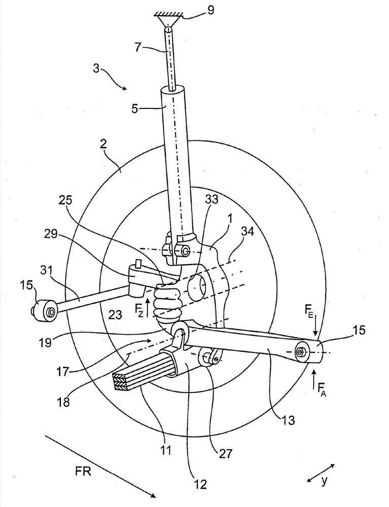
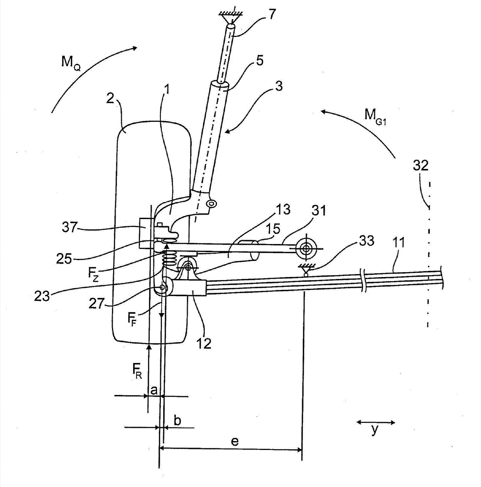
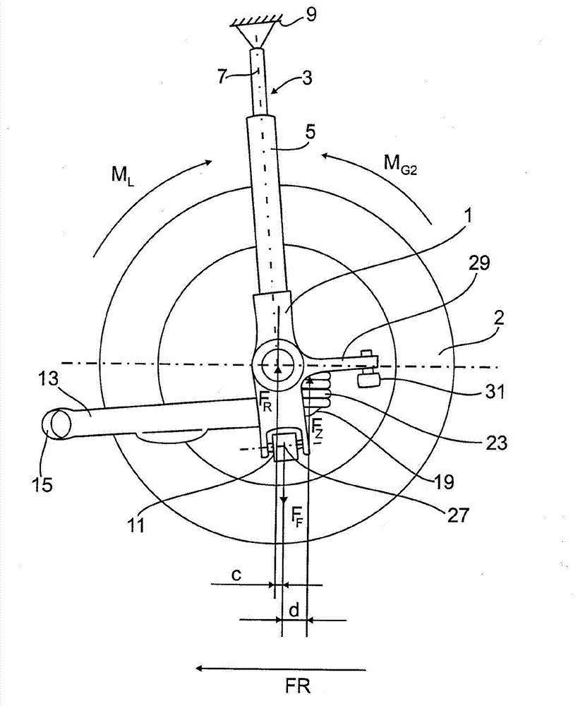
[0017] figure 1 shows a wheel suspension arrangement according to a first exemplary embodiment for a rear axle with a rear wheel drive not shown. The wheel suspension has a MacPherson suspension with a half-shell hub carrier 1 for the rear wheel 2 . Screwed onto the upper end of the hub carrier 1 is a substantially vertically arranged damper strut 3 comprising a damper tube 5 and a piston rod 7 guided in the damper tube 5 . The free upper end of the piston rod 7 is hinged to the body 9 .

[0018] The hub carrier 1 is articulated to the body 9 via a control arm assembly which lies essentially in the plane of the lower control arm. according to figure 1 , the control arm assembly has a leaf spring or bending spring 11 extending in the vehicle transverse direction y, the leaf spring end piece 12 of which, in the form of a transverse control arm, is at the bottom at the connection point 27 on the wheel carrier side Hinged on the hub bracket 1. The leaf spring 11 , which consi...


PUM


Abstract

The wheel suspension has a suspension spring (11) and a damper (3) connected to a wheel carrier (1) of a vehicle. The wheel carrier is hinged to a vehicle body (9) over a wheel guiding element. The suspension spring is formed as a leaf spring, and the leaf spring is articulated as a wheel guide element on the wheel carrier. The leaf spring directly or indirectly bears an additional spring (23).

Description

technical field [0001] The invention relates to a wheel suspension arrangement for a vehicle according to the preamble of claim 1 . Background technique [0002] The spring strut assembly and the shock strut of the wheel suspension structure of the vehicle need to bend due to the forces exerted on the wheel, whereby increased friction occurs between the piston rod of the shock absorber and the shock absorber tube. For the shock strut shaft, this leads to the so-called stick-slip effect (Stick-Slip-Effekt), that is to say, it causes the piston rod in the shock absorber tube to become stuck, thus reducing the response of the shock absorber sensitivity. [0003] In order to reduce this effect, a wheel suspension for vehicles is known from DE 102 006 022 151 A1, in which the wheel hub carrier is supported by auxiliary springs supported by wheel guide elements. By means of the auxiliary spring, the tilting moment acting on the shock absorber, which is produced by the wheel bear...

Claims


Application Information

Patent Timeline
Patent Type & Authority Applications(China)
IPC IPC(8): B60G3/28B60G3/18
CPCB60G2204/148B60G11/10B60G11/36B60G2200/1422B60G7/008B60G2200/141B60G2204/121B60G2204/1244B60G2206/15B60G11/08B60G3/28B60G2202/114B60G2206/50
Inventor H・穆勒W・施密特W・施密德
Owner AUDI AG
Learn More