Non-cooperative target docking mechanism with peripheral swing-rod-type expansion joint

A non-cooperative target and docking mechanism technology, applied in the field of non-cooperative target docking mechanism, can solve the problems of heavy weight, large size, complex structure, etc., and achieve the effect of light weight, high integration, and simple drive control

Inactive Publication Date: 2013-01-02
黄刚
View PDF6 Cites 21 Cited by
  • Summary
  • Abstract
  • Description
  • Claims
  • Application Information

AI Technical Summary

Problems solved by technology

[0003] The purpose of the present invention is to provide a non-cooperative target docking mechanism of the peripheral swing rod type expansion head to solve the problem that the existing non-cooperative target do...

Method used


Image

  • Non-cooperative target docking mechanism with peripheral swing-rod-type expansion joint
  • Non-cooperative target docking mechanism with peripheral swing-rod-type expansion joint
  • Non-cooperative target docking mechanism with peripheral swing-rod-type expansion joint

Examples


specific Embodiment approach 1

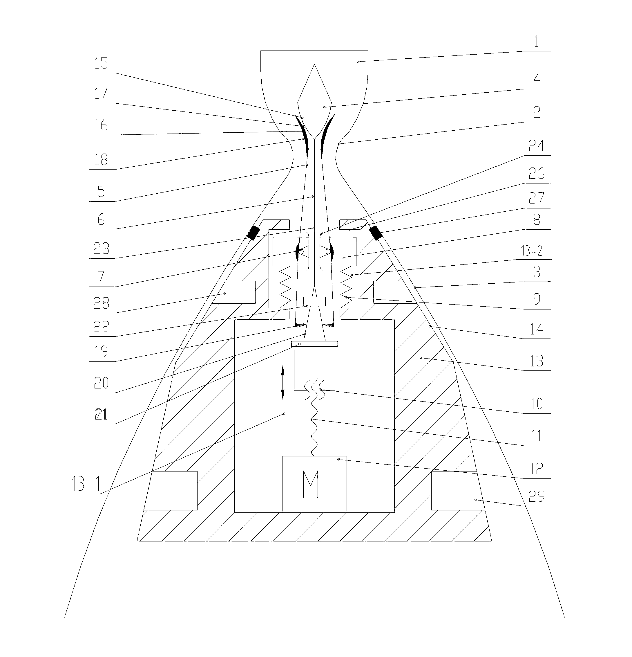
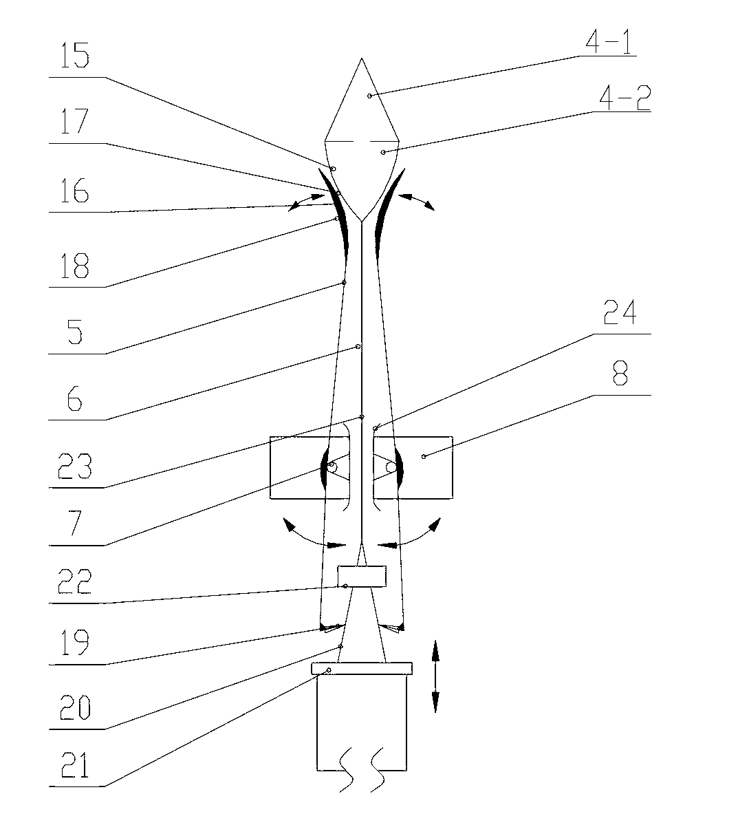
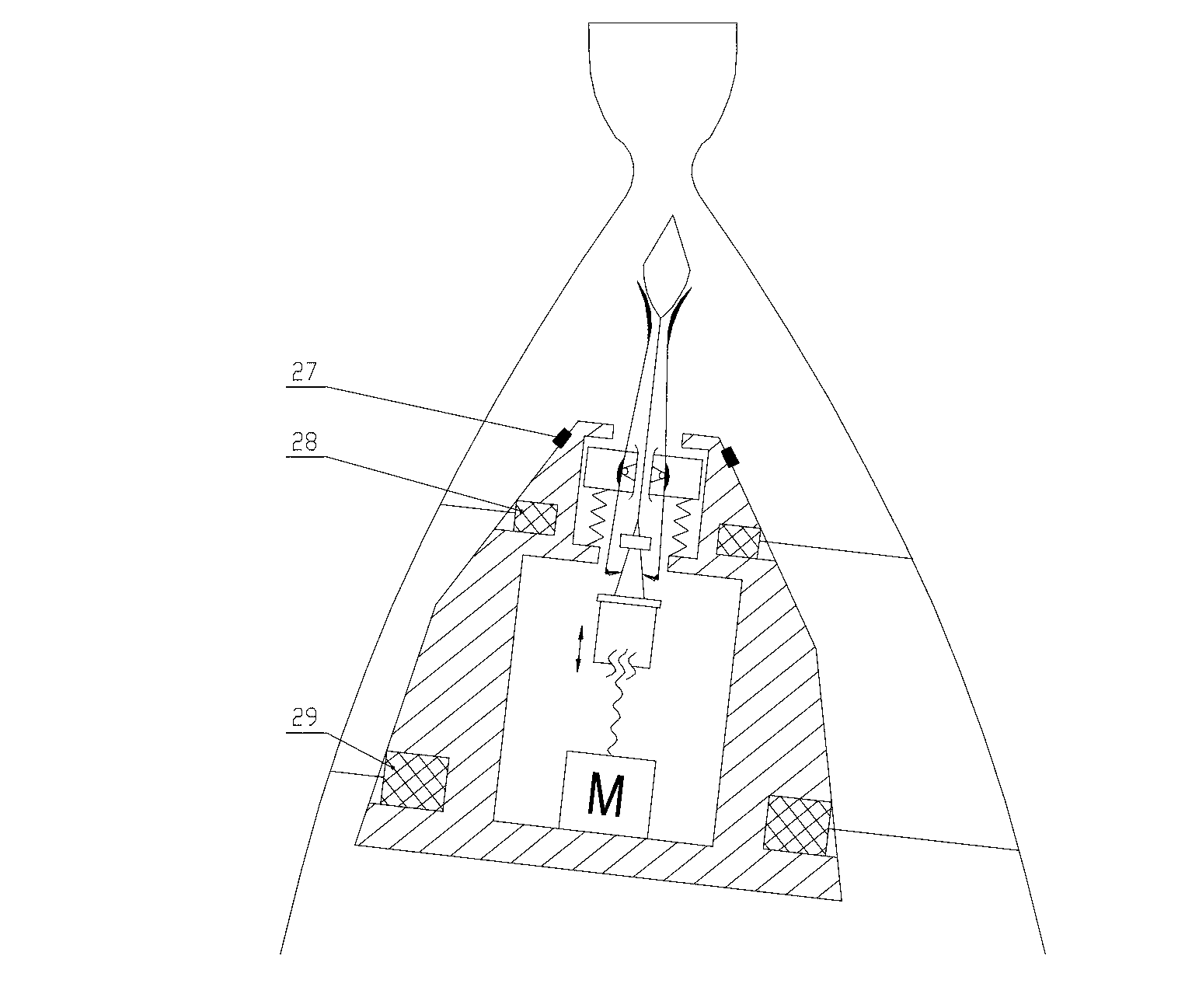
[0008] Specific implementation mode one: combine Figure 1-Figure 5 Describe this embodiment, the mechanism of this embodiment includes a cone top 4, a swing rod shaft 7, a locking slider 8, a return spring 9, a screw nut 10, a screw 11, a motor 12, a housing 13, a swing rod top 16, Fork hook 19, cone slide 20, lower limiter 21, upper limiter 22, slide bar 23, sleeve 24, slide limiter 26 and a plurality of fork 5, cone top 4 is formed by upper cone 4- 1 and the bottom surface of the lower cone 4-2 are butted into one body, the first groove 13-1 and the second groove 13-2 are arranged in the housing 13 and both the first groove 13-1 and the second groove 13-2 Connected, the upper part of the first groove 13-1 is provided with a sliding limiter 26, the upper part of the housing 13 is provided with a pressing surface 14 matching the inner wall of the nozzle 1, and the motor 12 is fixed in the first groove 13-1. 1, the output end of the motor 12 is rotationally connected to one e...

specific Embodiment approach 2

[0011] Specific implementation mode two: combination figure 1 To describe this embodiment, the number of swing bars 5 in this embodiment is 3-5. After the casing 13 presses the inner wall 3 of the diffuser section of the nozzle 1, the cone top 4 presses the swing rod top 16 to the throat 2 of the nozzle 1, and the number of swing rods 5 is 3-5, which can meet the pressing function needs. Other implementation manners are the same as the specific implementation manner 1.

specific Embodiment approach 3

[0012] Specific implementation mode three: combination figure 1 Describe this embodiment, the pretightening force of the back-moving spring 9 of this embodiment is 5-10N, has guaranteed the frictional force of swing rod top inner surface 17 and cone top sliding surface 15 and the friction of swing rod hook 19 and cone slider 20 The resultant force of the force is smaller than the reset force applied to the locking slider 8 by the reset spring 9 . Other implementation manners are the same as the specific implementation manner 1.


PUM


Abstract

The invention relates to a non-cooperative target docking mechanism with a peripheral swing-rod-type expansion joint, which aims to solve the problems of the complex structure, large size, heavy weight, and limitation on the application in the missions of 'GEO (geostationary orbit) protection' and 'in-orbit maintenance' of the present non-cooperative target docking mechanism. The mechanism realizes the rotation around a rotary shaft via the contact and the interaction of a swing rod, a slide surface and a conical inclined surface to finish the expansion and folding functions of a swing rod and realize docking and docking unlocking. An expansion mechanism is used for docking a throat structure of the inner surface of a spray tube, and after the swing rod is expanded, the docking rigidity is ensured by virtue of the compression surfaces of a locking slider and a shell, thereby realizing a docking function. The mechanism performs stepping by virtue of the expansion of the swing rod caused by a return spring and the locking movement of the locking slider, so that the control on the locking movement is simple. The mechanism disclosed by the invention is used for the field of aeronautics and astronautics.

Description

technical field [0001] The invention relates to a non-cooperative target docking mechanism. Background technique [0002] The non-cooperative target docking mechanism is a key device for capturing and docking non-cooperative space targets and completing the tasks of "GEO orbit protection" and "GEO satellite on-orbit maintenance". Geostationary orbit (GEO) is the only unique satellite orbit for human beings, and it is an extremely precious orbital resource. Geostationary orbit resources are becoming increasingly scarce, and the requirements for "GEO orbit protection" and "GEO satellite on-orbit maintenance" are becoming increasingly urgent. Space agencies performing tasks in the space environment should have high reliability, so space agencies should strive to have the characteristics of simple structure, small size, and light weight. The non-cooperative target satellite in space does not have a pre-designed docking interface, and the apogee engine (AKM) nozzle of the non-c...

Claims


Application Information

Patent Timeline
IPC IPC(8): B64G1/64
Inventor 黄刚张禹
Owner 黄刚
Why Eureka
Try Eureka