Flow control valve

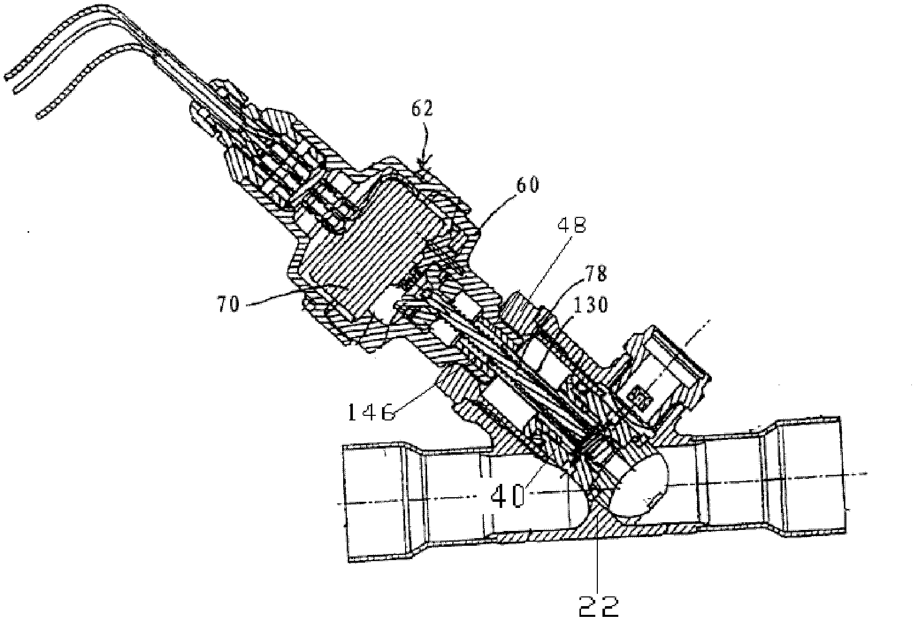
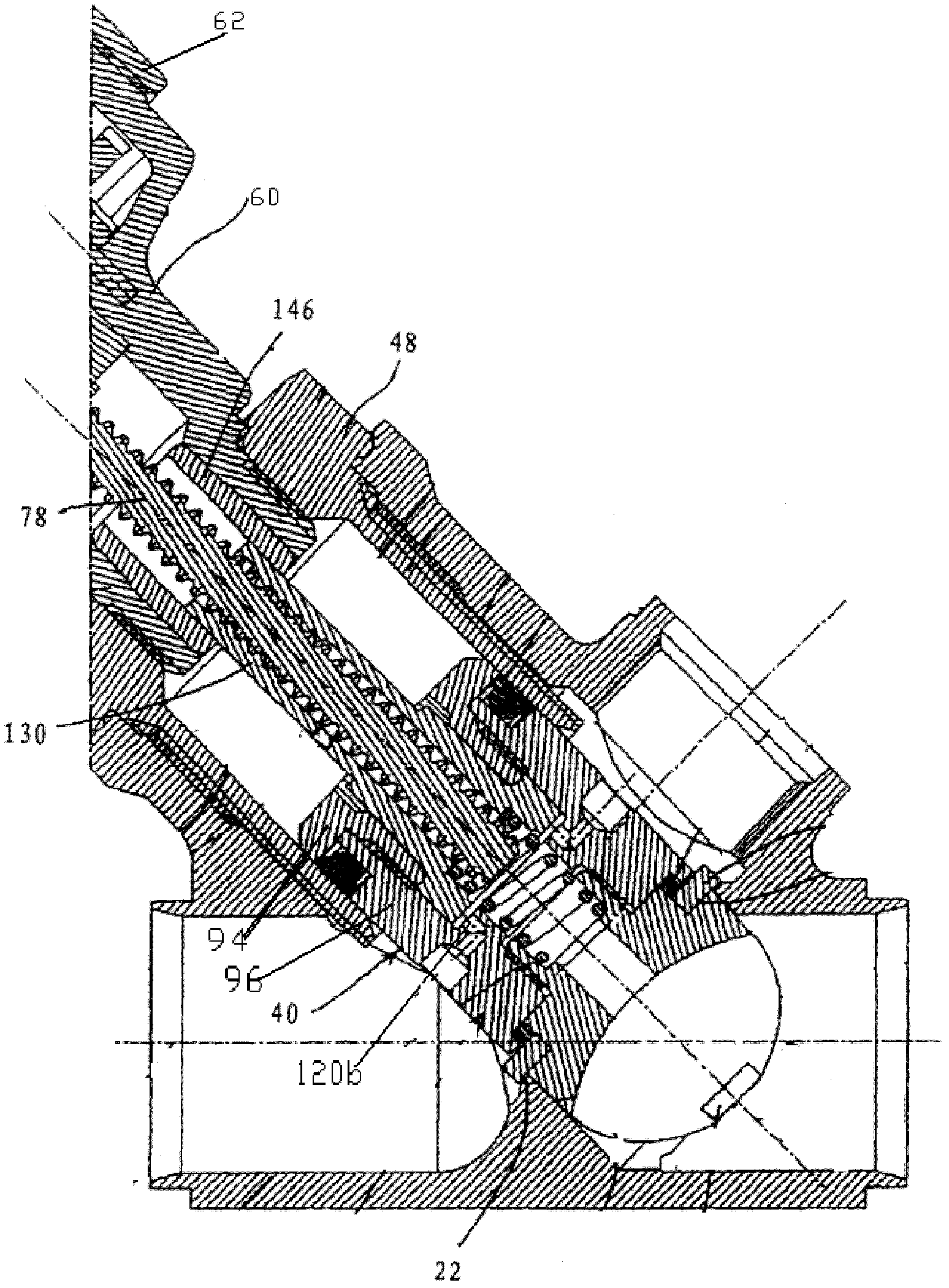
一种流量调节阀、阀座的技术,应用在流量调节阀领域,能够解决大同轴度误差、驱动轴78绕度大、材料成本增加等问题,达到消除同轴度误差、避免松动问题、可靠性提高的效果

Active Publication Date: 2013-01-02
ZHEJIANG SANHUA COMMERCIAL REFRIGERATION CONTROLS CO LTD SHAOXING CITY
View PDF10 Cites 15 Cited by
  • Summary
  • Abstract
  • Description
  • Claims
  • Application Information

AI Technical Summary

Problems solved by technology

The processing and assembly of the various parts of the valve body will bring a large coaxiality error, so that there is a large coaxiality error between the drive shaft 78 and the discharge piston 130. Since the discharge piston 130 cannot shake in the radial direction, Thereby it is easy to cause the drive shaft 78 to be stuck;
[0006] Second, the rear part 94 and the middle part 96 are connected by thread fit. As the discharge piston 130 and the valve unit 40 move in the axial direction, the thread fit is prone to loosening, resulting in reliable axial positioning of the discharge piston 130. less sexual;
[0007] Third, the discharge piston 130 needs to be fixed in the sleeve 146 of the lower housing 60, and is restricted from rotating in the circumferential direction by the sleeve 146, so the discharge piston 130 needs to protrude from the valve unit 40 to a sufficient length to extend into the sleeve 146; this kind of structural design makes the drive shaft 78 matched with the discharge piston 130 also have a larger length, resulting in a large degree of winding of the drive shaft 78, and the coaxiality of the discharge piston 130 and the drive shaft 78 when assembled Difficult to guarantee, if the installation is biased, the resistance torque will be increased, and even the drive shaft 78 will be stuck;
[0008] Fourth, as mentioned above, the discharge piston 130 needs to protrude from the valve unit 40 to a sufficient length so as to penetrate into the sleeve 146, and accordingly, the drive shaft 78 and the lower housing 60 will have a relatively large gap in the axial direction. Large length, thus resulting in increased material costs

Method used


Image

  • Flow control valve
  • Flow control valve
  • Flow control valve

Examples


Embodiment Construction

[0048] The core of the present invention is to provide a flow regulating valve. On the one hand, the structural design of the flow regulating valve can eliminate the coaxiality error between the screw rod and the nut caused by the processing and assembly of parts, and on the other hand, it can improve the nut. Reliability of axial limit.

[0049] In order to enable those skilled in the art to better understand the technical solutions of the present invention, the present invention will be further described in detail below in conjunction with the accompanying drawings and specific embodiments.

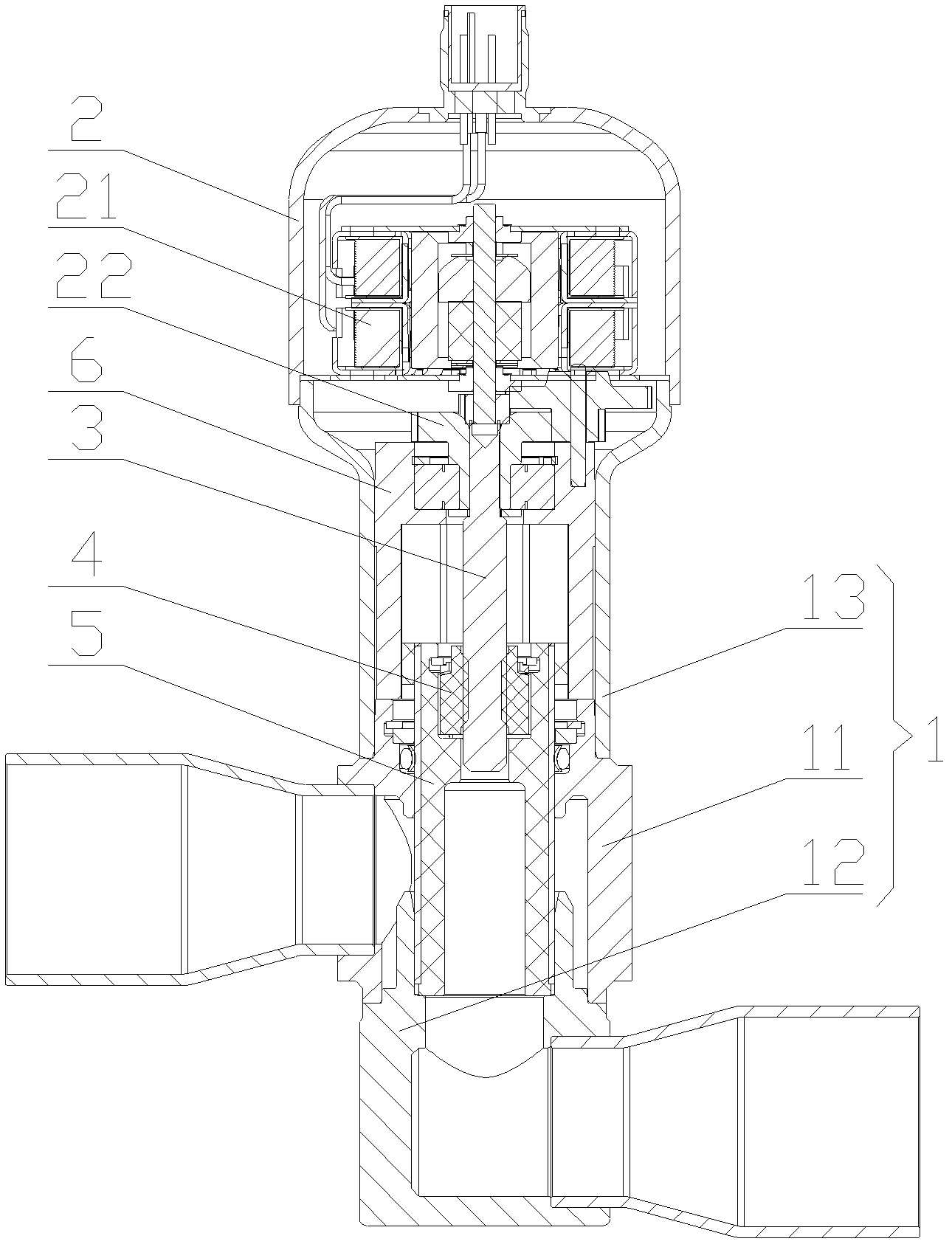
[0050] Please also refer to Figure 3 to Figure 4-4 , image 3 It is a structural schematic diagram of the flow regulating valve in the first embodiment of the present invention; Figure 4 for image 3 Schematic diagram of the structure of the valve stem of the medium flow regulating valve; Pic 4-1 for Figure 4 Sectional view of the valve stem; Figure 4-2 for Pic 4-1 Exploded...


PUM


Abstract

The invention discloses a flow control valve. The flow control valve comprises a valve seat (1) and a shell (2), wherein a motor (21) is arranged inside the shell (2) and is connected with a screw rod (3) by the output shaft of the motor; the screw rod (3) is connected with a nut (4); the nut (4) is connected with a valve rod (5); an installation groove (51) is arranged inside the valve rod (5); the nut (4) is in radial clearance fit in the installation groove (51); a ring-shaped limiting groove (52) is arranged on the inner wall of the installation groove (51); and a limiting part (53) which axially limits the nut (4) and is in clearance fit outside the nut (4) is arranged in the ring-shaped limiting groove (52). The flow control valve has the following beneficial effects that through the structural design, on the one hand, the coaxiality errors between the screw rod and the nut, which are caused by part processing and assembling, can be eliminated, and on the other hand, the axial limiting reliability of the nut can be improved.

Description

technical field [0001] The invention relates to the technical field of fluid control components, in particular to a flow regulating valve. Background technique [0002] The flow regulating valve is an important part of the refrigeration system, and it is another basic part of the four basic components of the refrigeration system except the evaporator, compressor and condenser. The working process of the flow regulating valve is generally: as the coil device is energized or de-energized, the valve needle adjusts the opening of the valve port, thereby adjusting the flow of the refrigerant. In addition, flow control valves are also widely used in other fluid control fields such as hydraulic systems and oil transportation. [0003] In the prior art, Chinese patent No. 200580023202.7 discloses a flow regulating valve; specifically, please refer to figure 1 with figure 2 , figure 1 It is a structural schematic diagram of a flow regulating valve in the prior art, figure 2 fo...

Claims


Application Information

Patent Timeline
Patent Type & Authority Applications(China)
IPC IPC(8): F16K3/30F16K31/50F16K31/53
CPCF16K31/04F16K31/508F16K31/047Y02B30/70F25B41/35F16K31/504F16K31/53
Inventor 不公告发明人
Owner ZHEJIANG SANHUA COMMERCIAL REFRIGERATION CONTROLS CO LTD SHAOXING CITY
Why Eureka
Try Eureka