Backlight module

A backlight module and component technology, applied in optics, light guides, light sources, etc., can solve problems such as light spots on the light guide plate, and achieve the effect of improving the display effect and increasing the space for light mixing

Inactive Publication Date: 2013-01-02
TCL CHINA STAR OPTOELECTRONICS TECH CO LTD
View PDF0 Cites 6 Cited by
  • Summary
  • Abstract
  • Description
  • Claims
  • Application Information

AI Technical Summary

Problems solved by technology

[0006] The technical problem to be solved by the present invention is to solve the problem that the extension direction of the light guide prism of the light guide plate is perpendicular to the extension direction of the prism above the light guide plate in the prior art, which causes the large-angle light beam of the light guide plate to be led out by the prism and cause light spots to appear. Provide a backlight module

Method used


Image

  • Backlight module
  • Backlight module
  • Backlight module

Examples


Embodiment Construction

[0032] In order to make the object, technical solution and advantages of the present invention clearer, the present invention will be further described in detail below in conjunction with the accompanying drawings and embodiments. It should be understood that the specific embodiments described here are only used to explain the present invention, not to limit the present invention.

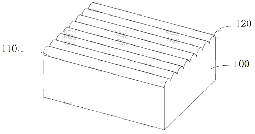
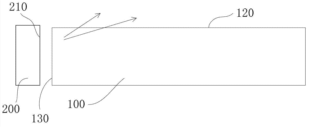
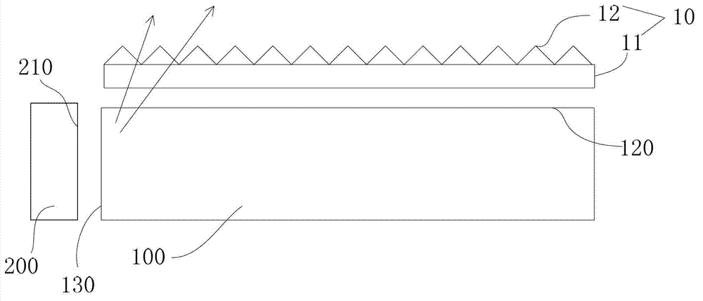
[0033] Figure 5 shows a schematic structural diagram of a backlight module according to an embodiment of the present invention, Figure 6 show Figure 5 A cross-sectional schematic diagram of A, combined with Figure 5 and 6 As shown, the backlight module according to the embodiment of the present invention includes a light emitting device 200 , a light guide plate 100 , a first prism assembly 300 and a second prism assembly 400 .

[0034] The light emitting device 200 includes a plurality of LED light sources, and the light beams emitted by the LED light sources are emitted in a direction app...


PUM


Abstract

The invention discloses a backlight module, which comprises a light emitting device, a light guide plate, a first prism component and a second prism component, wherein a light emergent top surface of the light guide plate is provided with a plurality of parallel adjacent light guide prisms; the light guide prisms extend in light emergent direction of the light emitting device; the first prism component comprises a first substrate and a plurality of parallel adjacent first prisms which are arranged on a light emergent surface of the first substrate; the first prisms extend in light emergent direction of the light emitting device; the second prism component comprises a second substrate and a plurality of parallel adjacent second prisms; the second prisms are arranged on a light emergent surface of the second substrate; and the extension direction of the second prisms is perpendicular to the extension direction of the first prisms. By arranging the first prisms with the same extension direction (or called parallel extension directions) above the light guide plate with the light guide prisms, light with large angle in the light guide plate is not led out on the light incidence side, so that a light mixing space is expanded, a shot spot phenomenon with clear brightness and darkness on the light incidence side is avoided, and the display effect of the backlight module is improved.

Description

technical field [0001] The invention relates to a flat panel display, in particular to a backlight module used for a flat panel display. Background technique [0002] With the continuous improvement of LED efficiency, the design of LED TV backlights has also evolved. From the initial four-sided light input, to double-side light input, to single-side light input, short-side light input has gradually become a trend. In addition, the frame of LED TV is becoming narrower and narrower in pursuit of aesthetics. With the development of light guide plate technology, more and more designs will be equipped with light guide plates containing microstructures. figure 1 A schematic diagram of the structure of the light guide plate is shown, as figure 1 As shown, the light-emitting top surface 110 of the light guide plate 100 has a plurality of parallel adjacent light guide prisms 120, and the light guide prisms 120 extend along a certain direction on the light guide plate, for example ...

Claims


Application Information

Patent Timeline
Patent Type & Authority Applications(China)
IPC IPC(8): F21S8/00F21V8/00F21V5/02F21V5/08F21Y101/02
CPCG02B6/0053G02F1/133615
Inventor 贺虎张光耀
Owner TCL CHINA STAR OPTOELECTRONICS TECH CO LTD
Why Eureka
Try Eureka