Infrared environmental gas remote sensing method and infrared environmental gas remote sensing device

An ambient gas and gas sensor technology, which is applied to measurement devices, material analysis through optical means, instruments, etc., can solve problems such as affecting the accuracy of gas monitoring, unable to correctly reflect the distribution of the measured gas, etc., and achieve the effect of accurate monitoring results.

Inactive Publication Date: 2013-01-02
CHINA UNIV OF MINING & TECH
View PDF7 Cites 2 Cited by
  • Summary
  • Abstract
  • Description
  • Claims
  • Application Information

AI Technical Summary

Problems solved by technology

These two methods have two serious shortcomings. First, the dust and moisture in the environment will absorb infrared light, which will affect the accuracy of gas monitoring; second, the measured gas concentration calculated by infrared light loss is It is assumed that the ideal condition of the measured gas concentration between the infrared transmitter and the infrared receiver (or reflector) is the same, which cannot correctly reflect the distribution of the measured gas in the remote sensing space

Method used


Image

  • Infrared environmental gas remote sensing method and infrared environmental gas remote sensing device
  • Infrared environmental gas remote sensing method and infrared environmental gas remote sensing device
  • Infrared environmental gas remote sensing method and infrared environmental gas remote sensing device

Examples


Embodiment 1

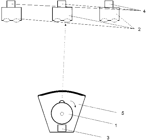
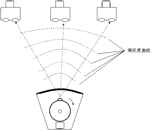
[0016] Embodiment 1: Infrared environmental gas remote sensing includes methods and devices, and the device includes: infrared transmitter 1, infrared receiver 2, transmitter infrared gas sensor 3, receiver infrared gas sensor 4 and rotating platform 5; infrared transmitter 1 and The infrared gas sensor 3 at the transmitting end is installed on the rotating platform 5; the infrared receiver 2 has two infrared receiving windows, which are respectively the first infrared receiving window 6 and the second infrared receiving window 7, wherein the first infrared receiving window An ordinary lens is installed on 6, a filter is installed on the second infrared receiving window 7, the first photoelectric receiving tube 8 is connected to the corresponding part of the first infrared receiving window 6, and the second photoelectric receiving tube 8 is connected to the corresponding part of the second infrared receiving window 7 Pipe 9, the output end of the first photoelectric receiving t...


PUM


Abstract

The invention relates to an infrared environmental gas remote sensing method and an infrared environmental gas remote sensing device, which belongs to the environmental gas monitoring method and the environmental gas monitoring device. An infrared transmitter and a transmitting-end infrared gas sensor of the device are installed on a rotary holder; an infrared receiver is provided with two infrared receiving windows, i.e. a first infrared receiving window and a second infrared receiving window, a first photoelectric receiving pipe is correspondently connected with the first infrared receiving window, a second photoelectric receiving pipe is correspondently connected with the second infrared receiving window, and both the output end of the first photoelectric receiving pipe and the output end of the second photoelectric receiving pipe are connected with the input end of a signal processor; a receiving-end infrared gas sensor is connected onto the infrared receiver; and the rotary holder is provided with a stepper motor. The detection method comprises the following steps of detection of average concentration and acquisition of gas distribution information. The infrared environmental gas remote sensing method and the infrared environmental gas remote sensing device have advantages that the environmental gas which is distributed in a space can be monitored, the interference problems of the environmental dust and moisture can be well solved, and the method and the device are suitable for the gas monitoring in the fields such as a security environment, carbon emission, environmental protection and the like.

Description

technical field [0001] The invention relates to an ambient gas monitoring method and device, in particular to an infrared ambient gas remote sensing method and device. technical background [0002] Using infrared detection principle to monitor ambient gas is a promising method. At present, there are generally two methods for infrared remote sensing to monitor atmospheric environment, one is reflection method and the other is direct radiation method. The first reflection method is that the infrared transmitter and infrared receiver are at one end, and the reflector is at the other end. and the loss caused by gas absorption on the reflection path, and calculate the concentration of the measured gas in the environment; the second direct method is that the infrared transmitter is at one end, the infrared receiver is at the other end, and the infrared transmitter is aligned with the infrared receiver to emit Infrared light, the infrared receiver receives the infrared light emitt...

Claims


Application Information

Patent Timeline
Patent Type & Authority Applications(China)
IPC IPC(8): G01N21/17
Inventor 童紫原童敏明李猛
Owner CHINA UNIV OF MINING & TECH
Why Eureka
Try Eureka