Frequency selection composite material and frequency selection antenna housing and antenna system made of frequency selection composite material

A technology of frequency selection and composite materials, which is applied in the direction of antennas, radiation unit covers, waveguide devices, etc., can solve the problems of electromagnetic energy loss and radar system detection, and achieve improved wave transmission performance, good wave transmission performance, and reflection The effect of shrinking

Active Publication Date: 2013-01-02
KUANG CHI INST OF ADVANCED TECH
View PDF2 Cites 10 Cited by
  • Summary
  • Abstract
  • Description
  • Claims
  • Application Information

AI Technical Summary

Problems solved by technology

However, the radome is an obstacle in the propagation direction of the electromagnetic wave emitted by the antenna. When the electromagnetic wave passes by, it will not only be reflected, but also absorbed by the radome, resulting in the loss of electromagnetic energy.
In addition, most of the current radome is a full-bandpass radome. When it is used in the radar system of the flying platform, because it works in the low frequency band, it will generate resonance in the high frequency band, accompanied by the appearance of grating lobes. At this time, the radar scattering cross section ( The English name is Radar Cross Section, referred to as RCS) is relatively large, when the high-frequency electromagnetic wave and / or incident at a certain angle of incidence, the radar system is easily detected by the enemy's high-frequency signal

Method used


Image

  • Frequency selection composite material and frequency selection antenna housing and antenna system made of frequency selection composite material
  • Frequency selection composite material and frequency selection antenna housing and antenna system made of frequency selection composite material
  • Frequency selection composite material and frequency selection antenna housing and antenna system made of frequency selection composite material

Examples


Embodiment Construction

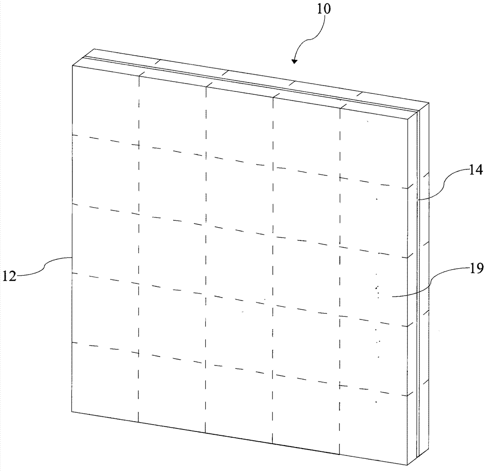
[0028] Terms such as "sheet", "layer", and "plate" in the present invention refer to thin-layer materials of arbitrary shapes such as planes, curved surfaces, conical surfaces, spherical surfaces, special-shaped surfaces, etc., and may also include soft films, depending on application requirements. different. For the sake of brevity, the "composite sheet", "layer", and "board" in this embodiment are all shown in a plane.

[0029] like figure 1 As shown, the frequency selective composite material of the present invention includes at least one composite sheet 10 , and the composite sheet 10 includes two dielectric substrates 12 bonded together and a structural layer 14 placed between the two dielectric substrates 12 . The two dielectric substrates 12 are made of polymer material, ceramic material, ferroelectric material, ferrite material or ferromagnetic material, such as epoxy resin glass fiber cloth (ie FR4), polytetrafluoroethylene (English name is Polytetrafluoroethene , r...


PUM


Abstract

The invention relates to a frequency selection composite material. The material comprises a composite sheet layer, wherein the composite sheet layer comprises two medium base plates and a structure layer which is arranged between the two medium base plates, the structure layer comprises a plurality of first discontinuous metal wires which are parallel to one another, each of the discontinuous metal wires comprises a plurality of wire segments which are arranged at intervals, the lengths of the first discontinuous metal wires are equal, the widths of the first discontinuous metal wires are equal, and the distances between any two adjacent ends of any two adjacent wire segments are equal; the distances between any first discontinuous metal wires and adjacent first discontinuous metal wires are equal, two corresponding ends of wire segments of corresponding positions of any two adjacent first discontinuous metal wires are flush with each other, the composite material is low in reflection and high in wave transmission rate for low-frequency range electromagnetic waves, so that the material has good wave transmission performance, and at the same time, the material can inhibit high-frequency stage electromagnetic waves and has a band elimination function, so that the material has low-pass high-resistance frequency-selection selection characteristics. The invention also relates to a frequency selection antenna housing and an antenna system made of the frequency selection composite material.

Description

technical field [0001] The present invention relates to a frequency selective surface and a frequency selective radome and an antenna system made therefrom, and more particularly to a frequency selective composite material of novel design and a frequency selective radome and an antenna system made therefrom. Background technique [0002] The radome is a structural part that protects the antenna from the harsh external environment, especially an important part of the radar system. Traditionally, the materials used to manufacture such radomes should have excellent wave-transmitting performance, stable high-temperature dielectric properties, low linear expansion coefficient, and resistance to particle cloud erosion. However, the radome is an obstacle in the propagation direction of the electromagnetic wave emitted by the antenna. When the electromagnetic wave passes by, it will not only be reflected, but also absorbed by the radome, resulting in the loss of electromagnetic ener...

Claims


Application Information

Patent Timeline
Patent Type & Authority Applications(China)
IPC IPC(8): H01Q15/00H01Q1/42H01P1/20
Inventor 刘若鹏赵治亚刘列黄涛
Owner KUANG CHI INST OF ADVANCED TECH
Why Eureka
Try Eureka