Wiring method for realizing direct-current deicing of ground wire of converter station

A technology of DC ice melting and wiring method, applied in the installation of cables, electrical components, overhead installation, etc., can solve the problems of rising output voltage of ice melting device, reduced lightning protection effect of ground wire, and rising cost of ice melting device, etc. Achieve the effect of flexible ground wire DC ice melting method, improved ice melting effect, and reduced cost of full insulation transformation

Active Publication Date: 2013-01-02
SOUTHWEST ELECTRIC POWER DESIGN INST OF CHINA POWER ENG CONSULTING GROUP CORP
View PDF2 Cites 10 Cited by
  • Summary
  • Abstract
  • Description
  • Claims
  • Application Information

AI Technical Summary

Problems solved by technology

However, due to the high resistance of the ground wire, if the ground wire is short-circuited at the end after the ground wire is fully insulated, and then the ice is melted, the required output voltage of the ice-melting device is high, so the insulation level of the ground wire has to be improved , and the improvement of the insulation level of the grou

Method used


Image

  • Wiring method for realizing direct-current deicing of ground wire of converter station
  • Wiring method for realizing direct-current deicing of ground wire of converter station
  • Wiring method for realizing direct-current deicing of ground wire of converter station

Examples


Embodiment 1

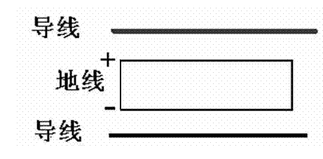
[0058] Example 1: figure 2 , which shows a schematic diagram of parallel wiring in which the ground wire is divided into one segment. When n is 1, it is only necessary to short-circuit a number of ground wires that are basically aligned with each other in the ground wire segment at the beginning and end, and connect wire 1 to the short-circuit point at the beginning of the ground wire at the beginning, and connect wire 2 to the beginning of the ground wire at the end. The ends of the ground wires are connected with a short-circuit point. The wires "+" and "-" marked in the figure are the output access points of the DC ice melting device. In the case of not considering the wire resistance (the wire resistance is negligible relative to the ground wire resistance), and there are two ground wires in the ground wire segment, it is assumed that the resistance of each ground wire is r, and the equivalent resistance is r / 2. When melting ice, the current on each branch of the gr...

Embodiment 2

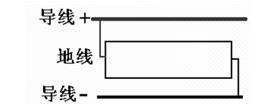
[0059] Example 2: image 3 The line structure when n is 2 is listed. When n is 2, the wiring implementation process is to divide the ground wire into two sections at 1 / 2 (insulation between the two sections), and short-circuit the ground wires at the beginning and end of each ground wire segment that are parallel to each other and basically aligned at both ends. , and connect the beginning of each ground segment to wire 1, and connect the end of each ground segment to wire 2. The wires marked with "+" and "-" in the figure are the output access points of the ice melting device. The resistance of a single ground wire in each ground wire segment is r / 2, and the definition of r is the same as that in Embodiment 1, which is the equivalent resistance of a whole single ground wire. In the case of not considering the wire resistance and there are two ground wires in the ground wire segment, the equivalent resistance of the ground wire after being segmented and connected in parallel...

Embodiment 3

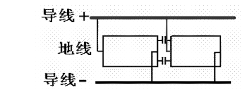
[0060] Embodiment 3: as Figure 4 , when n is 4, the wiring implementation process is to divide the ground wire into 4 segments (each segment is insulated), short-circuit a number of ground wires in each ground wire segment that are basically aligned with each other at both ends, and connect each The beginning of each ground segment is connected to wire 1 and will be connected to wire 2 at the end of each ground segment. The wires marked with "+" and "-" in the figure are the output access points of the ice melting device. The resistance of a single ground wire in each ground wire segment is r / 4, and the definition of r is the same as that in Embodiment 1. When the wire resistance is not considered and there are two ground wires in the ground wire segment, the ground wire is divided into It is 4 sections and the equivalent resistance r / 32 of parallel connection is 1 / 16 of embodiment 1. The output current of the DC ice-melting device is 8i, and the output voltage is u=ir / 4. C...


PUM


Abstract

The invention discloses a wiring method for realizing the direct-current deicing of a ground wire of a converter station, relates to a direct-current deicing technique of a power grid transmission line, and aims at providing a method for effectively reducing the equivalent resistance of the ground wire to be deiced. The technical points of the wiring method are as follows: the wiring method comprises a step of carrying out all-insulation transformation on the ground wire to be deiced, and retaining one grounding point at most after the all-insulation transformation; a step of dividing the ground wire into n sections, wherein each section of the ground wire comprises one ground wire or at least ground wires which are parallel to each other and two ends of which are aligned; a step of connecting one ends of all ground wires belonging to one same ground wire section by means of short circuits so as to be used as one end of the ground wire section, and connecting the other ends of all ground wires belonging to one same ground wire section by means of circuit boards so as to be used as the other end of the ground wire section; a step of connecting one ends of all the ground wire sections with a lead I and connecting the other ends of all the ground wire sections with a lead II; a step of connecting an output access point of a direct-current deicing device with the lead I; a step of connecting the output access point of the direct-current deicing device with the lead II, etc.

Description

technical field [0001] The invention relates to a DC ice-melting technology for power grid transmission lines, in particular to a wiring method for realizing DC ice-melting of a ground line of a converter station. Background technique [0002] The threat of ice disaster has always been a major technical problem that the power system industry is struggling to deal with. In recent years, with changes in global climate conditions, low-temperature, rainy, snowy and freezing weather has frequently occurred in southern, central, and northern China, which has repeatedly caused large-scale and long-term outages of power transmission lines in various provinces in our country, causing huge losses to the national economy and people's lives. . In order to prevent this situation from recurring, after the ice disaster in 2008, my country's electric power science and technology workers independently carried out the research and development of DC ice melting technology and devices, and suc...

Claims


Application Information

Patent Timeline
IPC IPC(8): H02G7/16
Inventor 吴怡敏邹家勇冯小明余波郑勇刘正道张映帧李龙才周德才严可为尹大千蔡德江朱大鹏
Owner SOUTHWEST ELECTRIC POWER DESIGN INST OF CHINA POWER ENG CONSULTING GROUP CORP
Why Eureka
Try Eureka