Air extraction device and method for removing particles carried by an air flow

A technology of air suction and air flow, applied in the direction of components, separation methods, chemical instruments and methods for pumping devices for elastic fluids, which can solve problems such as high fan ventilation volume, and achieve low current consumption and noise generation The effect of low and good separation ability

Active Publication Date: 2013-01-02
BERLING
View PDF4 Cites 3 Cited by
  • Summary
  • Abstract
  • Description
  • Claims
  • Application Information

AI Technical Summary

Problems solved by technology

The device leads to acceptable separation results, but still requires a relatively high fan airflow, and the operating noise is noticeably perceptible

Method used


Image

  • Air extraction device and method for removing particles carried by an air flow

Examples


Embodiment Construction

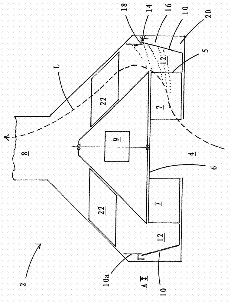
[0027] figure 1 A schematic cross-sectional view of the air suction device 2 is shown, through which an air flow L flows through an air guide channel formed in the air suction device 2 . Starting from the intake opening 4 in a first section, the air guide channel passes through a fan wheel 6 which can be driven by a motor 9 . The fan wheel 6 is provided with some air blades 7 . Through the rotational movement of the fan wheel 6 , the air flow L is accelerated in the radial direction outwards in the gaps between the individual air blades 7 and reaches its highest speed when it exits the fan wheel 6 . The rear edges, viewed in the direction of flow, of adjacent air blades 7 each delimit laterally an outflow opening 5 through which the air flow L exits the fan wheel 6 .

[0028] The throughflow space 12 directly adjoins the outflow opening 5 as part of the second section of the air guiding channel. The throughflow chamber 12 is delimited upstream by the outflow opening 5 and o...


PUM


Abstract

The invention relates to an air extraction device (2) comprising an intake opening (4), a downstream air duct for an air flow (L), said air duct extending in a first section through a rotatingly driven fan wheel (6) radially outward and extending in a second section downstream of the outlet openings (5) of the fan wheel (6) such that the air flow (L) is deviated in an approximately axial direction to the fan wheel (6), and runs into an exhaust opening (8). The second section has a lateral wall (10) that is arranged opposite to the outlet openings (5) of the fan wheel (6) at a distance thereto. The aim of the invention is to improve the capacity of the air extraction device. For this purpose, the second section comprises a through-flow compartment (12) arranged in the plane of rotation of the fan wheel (6) which compartment is arranged downstream of the outlet openings (5) of the fan wheel (6), which is radially limited by the lateral wall (10) and in which no air guideways are arranged.

Description

technical field [0001] The invention relates to an air suction device comprising a suction opening, an air guiding channel for an air flow adjoining the suction opening, the air guiding channel passing in a first section through a The rotationally driven fan wheel extends radially outwards, and the air guide channel adjoins the outflow opening of the fan wheel in a second section along approximately the axis relative to the fan wheel while deflecting the air flow. It extends in the direction and is designed to open into the outlet opening, wherein the fan wheel is designed such that the second section has a lateral wall which is situated opposite the outlet openings of the fan wheel at a distance. [0002] Furthermore, the invention relates to a method for separating particles entrained in an air flow, in which the air flow is conveyed and accelerated in the radial direction by means of a fan wheel, out of which the air flow is discharged and It is then steered into the axial...

Claims


Application Information

Patent Timeline
Patent Type & Authority Applications(China)
IPC IPC(8): F04D29/42F04D29/44F04D29/58F04D29/70B01D45/14F24C15/20
CPCF04D29/441B01D45/14F04D29/584F04D29/4253F04D29/703F24C15/20F05D2260/609F05D2210/12Y10S415/00Y10S417/00
Inventor U·贝尔林
Owner BERLING
Why Eureka
Try Eureka