Tilting furnace

A shell and discharge port technology, applied in the field of tilting furnaces, can solve the problems of maintenance material pollution, poisoning, and difficulty in accessing the discharge port, etc.

Active Publication Date: 2013-01-02
BELGOPROCESS
View PDF6 Cites 5 Cited by
  • Summary
  • Abstract
  • Description
  • Claims
  • Application Information

AI Technical Summary

Problems solved by technology

[0003] A disadvantage of this known furnace is that it is not possible to precisely control the discharge
Furthermore, inside the housing, the furnace includes a large number of moving parts that often require maintenance and are contaminated by the material in the f

Method used


Image

  • Tilting furnace
  • Tilting furnace
  • Tilting furnace

Examples


Example Embodiment

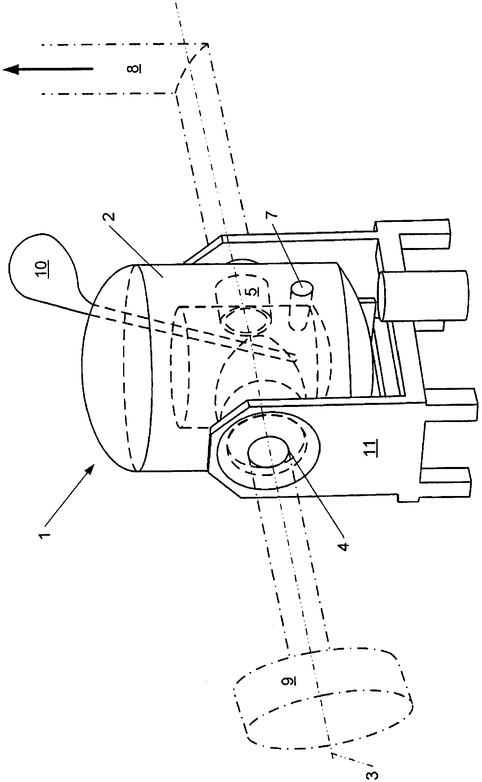
[0017] Hazardous materials such as radioactive or chemically hazardous waste must be brought to a stable state before they can be discharged and / or permanently stored. It is known to process such materials by gasification and / or melting at very high temperatures. If gasification of the material occurs in the presence of oxygen, combustion is predominantly carried out. However, some materials can also be converted to the gas phase in the absence of oxygen. The molten material will be in the form of vitrified slag or a mixture of metal and slag due to the very high temperature, for example up to 15000°C. Hazardous chemicals and / or radioactive compounds are generally contained in the vitrified slag. As a result vitrified slag is a more favorable state for storing this hazardous material in a dump or storage area.

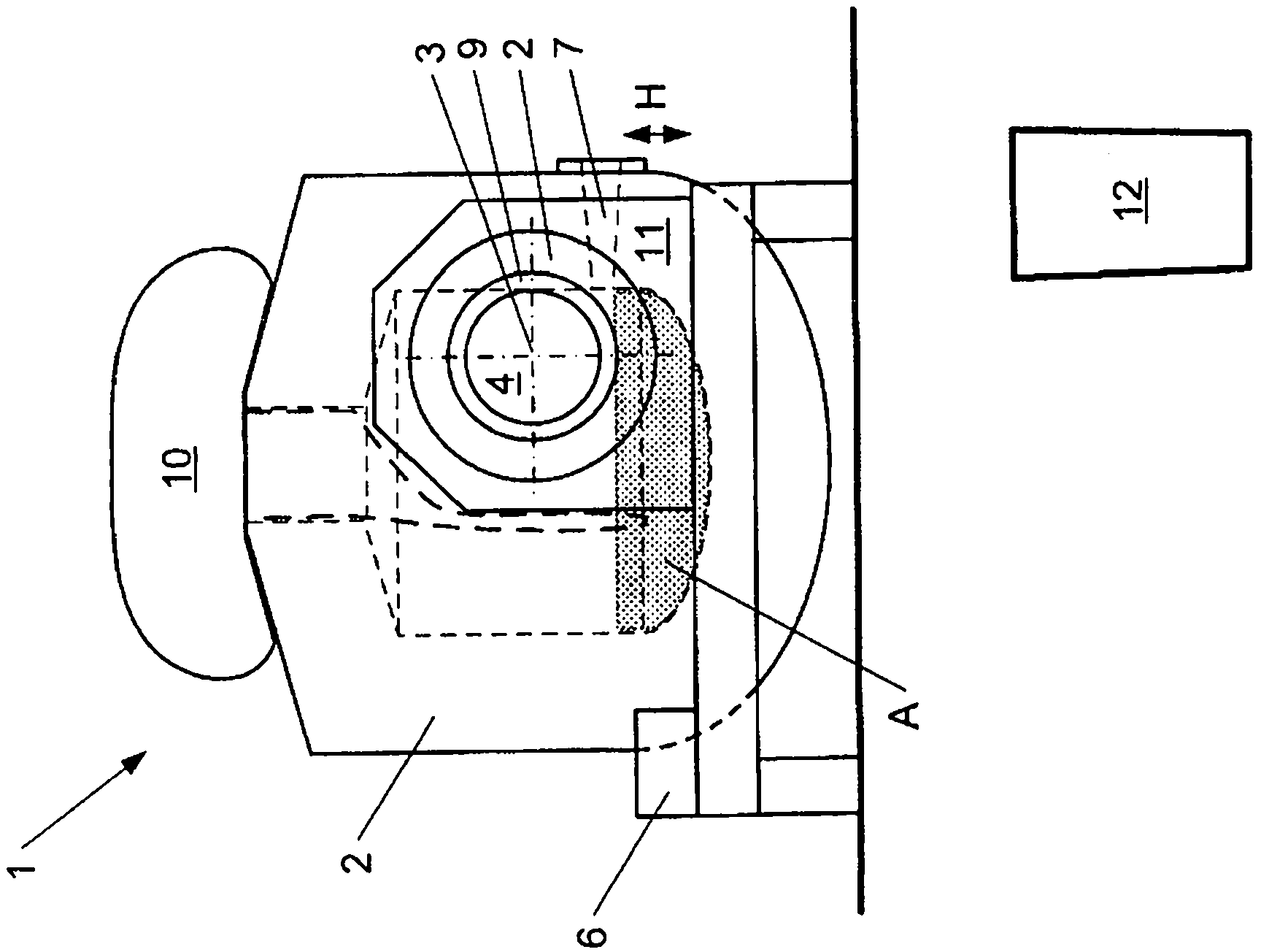
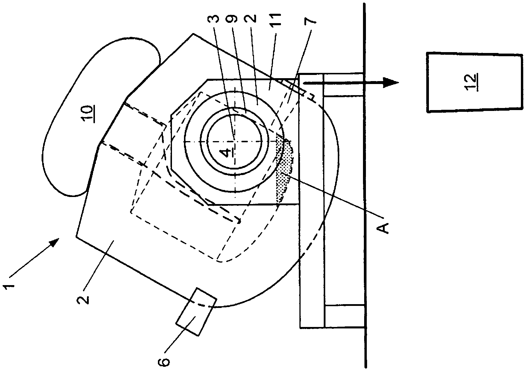
[0018] These very high temperatures can be achieved in a furnace 1 suitable for this. When handling hazardous materials, precautions must especially be considered ...


PUM


Abstract

A furnace 1 for melting and/or gasifying material, comprising a housing 2 for temporary enclosure of said material, a supply opening 3 through said housing 2, heating means 10, a discharge opening 7 through said housing 2, a gas outlet 5 through said housing 2, wherein said housing 2 is mounted tiltable around a horizontal axis 3, said supply opening 4 extending coaxially with said horizontal axis 3, and the discharge opening 7 being mounted in a wall of the housing 2 so that said melted material can be removed from the housing 2 by tilting the furnace 1 about said axis 3.

Description

technical field [0001] The invention relates to a furnace for melting and / or gasifying materials, especially toxic and / or radioactive materials, comprising a bowl-shaped housing for temporarily enclosing said materials, and having a supply which can be connected to a source of material an opening through the housing for introducing the material into the housing, a plasma gun intended to melt and / or vaporize the introduced material, through the housing A body with a discharge port for removing molten material from the housing, a gas outlet through the housing for removing gasified material from the housing. Background technique [0002] Such a furnace is known from WO 2005 / 052447. WO 2005 / 052447 describes a high-temperature furnace for burning and melting waste, especially toxic and radioactive waste, by means of a plasma gun. The shell of the furnace is shaped as a centrifuge. The centrifuge includes a bottom plate, a wall and a discharge port arranged on the bottom plate...

Claims


Application Information

Patent Timeline
IPC IPC(8): F23G5/08F23G7/00F23J1/08C03B5/00F27D3/00H05H1/48
CPCF23J1/08F23G2202/20F23G5/085F23G7/00C03B5/06C03B5/005F23G2204/201F23G2209/18H05H1/34F23G5/08F27B14/02F27B14/14F27B14/20F27D11/10F27D2021/0078
Inventor J·德克尔斯J·昂桑
Owner BELGOPROCESS
Why Eureka
Try Eureka