Hydraulically compressed molten steel flow control valve with side opening door

A technology of flow control valve and side door, which is used in manufacturing tools, casting melt containers, metal processing equipment, etc., can solve the problems of affecting the sliding of the sliding plate, complicated operation, unreasonable structure, etc., to improve safety performance and structural design. Simple, even pressure effect

Inactive Publication Date: 2013-01-09
河南省伯马股份有限公司
View PDF5 Cites 1 Cited by
  • Summary
  • Abstract
  • Description
  • Claims
  • Application Information

AI Technical Summary

Problems solved by technology

[0002] At present, the known molten steel flow control mechanism mainly relies on manual and hydraulic drive to realize the reciprocating operation of the movable frame in the fixed frame, thereby driving the reciprocating motion of the refractory sliding plate in the movable frame and the fixed frame, realizing the opening, closing, and semi-opening of the aperture, and controlling the flow of molten steel and flow rate, but due to the unreasonable structure, there is no positioning or clamping device, there are tolerances in the cooperation of the movable frame, the fixed frame, and the refractory slide plate, resulting in the slide plate not being fully opened, causing the slide plate to pull grooves during use, and the unreasonable fixation of the slide plate often leads to Radial cracks appear on refractory slides at high temperature, and these design defects directly affect the continuous sliding of the slides.
The traditional slide mechanism adopts the method of opening the door up and down to replace the slide plate, which has the disadvantages of high labor intensity, complicated operation, poor safety performance, and high-efficiency continuous casting without steelmaking, which affects the rhythm of steelmaking and the promotion of new steelmaking technologies

Method used


Image

  • Hydraulically compressed molten steel flow control valve with side opening door
  • Hydraulically compressed molten steel flow control valve with side opening door
  • Hydraulically compressed molten steel flow control valve with side opening door

Examples


Embodiment 1

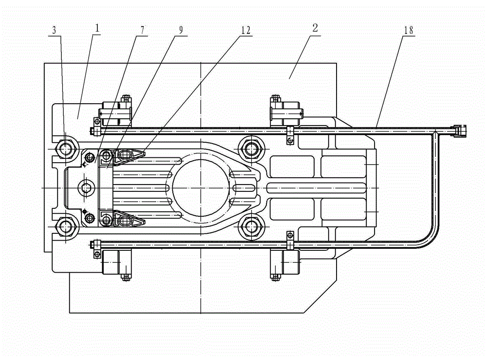
[0026] Embodiment one: see figure 1 , Figure 4 , Figure 7 , Figure 10 , Figure 12 , the liquid steel flow control valve of the hydraulic pressing side opening door of the present invention comprises a base 1, a moving frame 21, a pressing frame 30, and a combination of refractory materials. The sides are connected by a pivot 14, so that the compression frame and the motion frame can be centered on the connected side to form a side opening mode, which is convenient for refractory combination replacement. Base 1, motion frame 21 and compression frame 30 realize compression by spring combination, and described spring combination is made up of spring case 51, spiral spring 52, spring pull bar 53, spring pressing plate 54 and compression rod 55, and spring coil 52 and spring The pressing plate 54 is nested and installed in the spring box 51, and the spring box 51 and the pressing rod 55 are matched together by the spring pressing plate 54 and the spring pull rod 55. Both en...

Embodiment 2

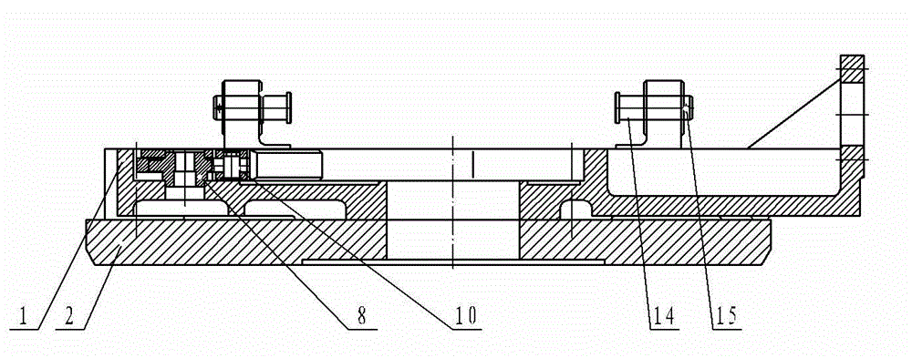
[0031] Embodiment two: see Figure 1 to Figure 12 , the liquid steel flow control valve with hydraulic pressure side opening in this embodiment is provided with a slide plate positioning point and a top-tight assembly respectively in the base and the longitudinal ends of the motion frame. (not shown), top clamping plate 9 and top clamping block 12, 10 in the figure is the hinge shaft of the top clamping block, 7 is the cam cover plate, when the upper slide plate is put into the base, turn the cam 8 with a special tool to make the spring act on force On the clamping block 12, the clamping block is moved longitudinally and pressed against the upper slide plate arranged in the base from the direction of the wedge angle; Figure 4 ~ Figure 6Among them, the lower plate jacking assembly in the motion frame includes a cam 26, a spring, a jacking plate 25 and a jacking block 23. In the figure, 24 is the hinge shaft of the jacking block, 29 is a cam cover plate, 20 is a guard plate, an...

Embodiment 3

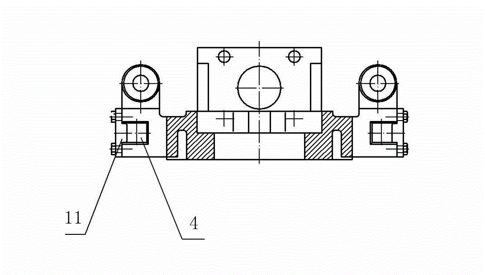
[0033] Embodiment three: see Figure 10 , Figure 11 The difference between the liquid steel flow control valve of this embodiment and the previous embodiments is that a convenient force application structure 58 for supporting the pressing rod is provided on the pressing rod 55 in cooperation with the bottom plate of the spring box 51, so that The force applying mechanism is designed as a stepped hole with a variable diameter. After the hydraulic gun is placed in the stepped hole, its movable part and fixed part can respectively press against the bottom plate of the spring box 51 or block the compression rod 55, so that the compression rod and The spring box is separated and the axles at both ends of the spring box are placed in the groove 4. At the same time, the coil spring produces the contraction force of the compression base and the compression frame, so that the upper and lower plates Create a steady pressure. The installation is quick, the pressure is constant after p...


PUM


Abstract

The invention relates to a molten steel flow and flow speed control mechanism in a steelmaking and casting process. The hydraulically compressed molten steel flow control valve with a side opening door comprises a base, a motion frame, a compressing frame and combination of refractory materials. The motion frame is arranged in the compressing frame in sliding match. The base, the motion frame and the compressing frame are compressed by spring combination which consists of a spring box, a spiral spring, a spring pull rod, a spring pressure plate and a compressing rod. The spring box and the compressing rod are matched and combined together through the spring pressure plate and the spring pull rod. Wheel shafts are arranged at both ends of the spring box and the compressing rod. Wheel shaft embedding grooves are respectively arranged on the base and the compressing frame. The mechanism is locked in such a manner that the spring in the spring combination is supported by a hydraulic operational gun, and the wheel shafts in the spring combination fall into the grooves on the compressing frame so as to form a stable pressure between upper and lower slide plates; then, the motion frame drives the upper slide plate to move in the base and the compressing frame to control the molten steel flow. The pressure of the spring compressed is constant, so that the hydraulically compressed molten steel flow control valve with the side opening door is stably operated.

Description

technical field [0001] The invention relates to a molten steel flow and velocity control mechanism in the steelmaking and casting process. In particular, it relates to a molten steel flow control valve combining machinery and refractory materials. Background technique [0002] At present, the known molten steel flow control mechanism mainly relies on manual and hydraulic drive to realize the reciprocating operation of the movable frame in the fixed frame, thereby driving the reciprocating motion of the refractory sliding plate in the movable frame and the fixed frame, realizing the opening, closing, and semi-opening of the aperture, and controlling the flow of molten steel and flow rate, but due to the unreasonable structure, there is no positioning or clamping device, and there are tolerances in the cooperation of the movable frame, the fixed frame, and the refractory slide plate, resulting in the slide plate not being able to be fully opened, causing the slide plate to pul...

Claims


Application Information

Patent Timeline
Patent Type & Authority Applications(China)
IPC IPC(8): B22D41/22
Inventor 吕培中党树丰王大军游佩玉张建民魏德鑫
Owner 河南省伯马股份有限公司
Why Eureka
Try Eureka