Double-wing type miniature bionic ornithopter

A flapper and miniature technology, applied in helicopters, motor vehicles, aircraft parts, etc., can solve the problems of asymmetric flapper motion, complex structure, high cost, etc., and achieve increased steering sensitivity, simple and compact structure, and reduced weight. Effect

Inactive Publication Date: 2013-01-09
SOUTHEAST UNIV
View PDF6 Cites 58 Cited by
  • Summary
  • Abstract
  • Description
  • Claims
  • Application Information

AI Technical Summary

Problems solved by technology

The flapping wing aircraft based on MEMS technology can reduce the weight of the body and achieve a real bionic effect, but its cost is relatively high and the technology is not mature enough
The traditional mechanical flapper has the advantages of low cost and mature manufacturing technology, but its structure is complex and consumes a lot of energy. Compared with the flapper processed by micromachining, its mass is often too large
The main problems of the current research on the micro-orthopter are: how to reduce the weight and volume of the body, how to increase the lift and attitude control
[0003] At p

Method used


Image

  • Double-wing type miniature bionic ornithopter
  • Double-wing type miniature bionic ornithopter
  • Double-wing type miniature bionic ornithopter

Examples


Embodiment Construction

[0023] The present invention will be described in further detail below in conjunction with the accompanying drawings and embodiments.

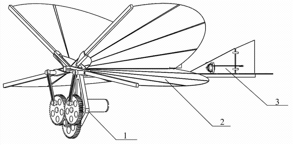
[0024] Such as figure 1 As shown, the bi-wing bionic flapping wing aircraft includes a driving mechanism 1, a double flapping wing mechanism 2, a tail mechanism 3 and a main arm (not visible in the figure), the driving mechanism is connected to the front end of the main arm, and the double flapping wing mechanism is located at the main Just above the arm, the empennage mechanism is connected to the just rear end of the main arm.

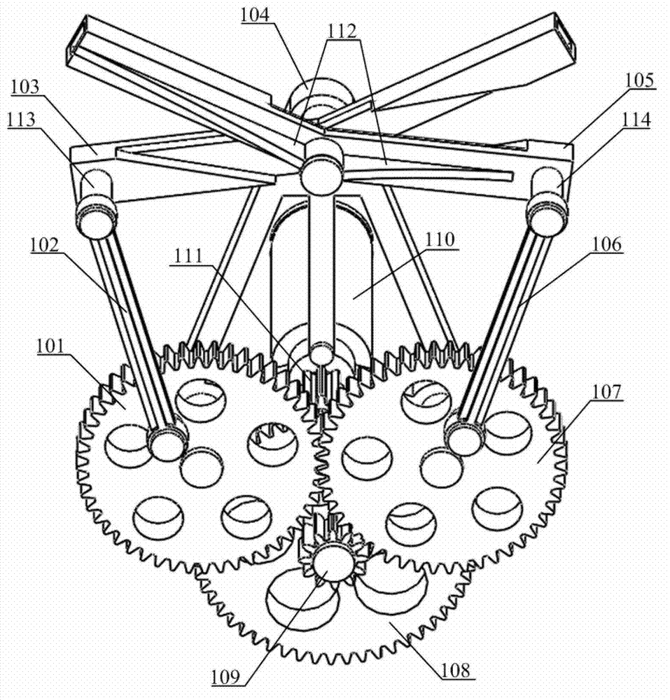
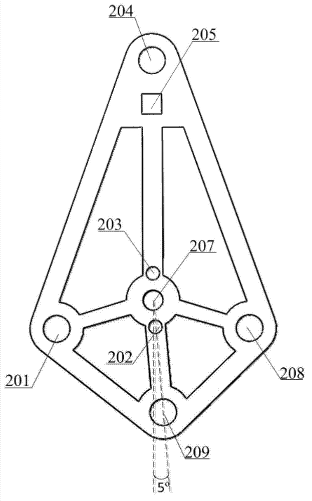
[0025] see figure 2 , 3 , the driving mechanism includes a diamond-shaped bracket, a micro DC motor, a gear reduction mechanism, two linkage mechanisms and two flapping wing frames. The rhombus bracket 104 is erected, and its four vertices are defined as upper vertices (with holes 204), lower vertices (with holes 209), left vertices (with holes 201), and right vertices (with holes 208), Support beams are arrange...


PUM


Abstract

The invention relates to a double-wing type miniature bionic ornithopter, which comprises a driving mechanism, a double-flapping-wing system, a spoiler mechanism and a principal arm, wherein the driving mechanism is just connected to the front end of the main arm, the double-flapping-wing system is positioned above the principal arm, and the spoiler mechanism is connected to the rear end of the principal arm. The driving mechanism comprises a diamond rack, a miniature direct current motor, a gear reducing mechanism and two crank-link mechanisms, the double-flapping-wing system comprises two symmetrical flapping wing racks, four flapping wing installation rods, an upper layer of flapping wing and a lower layer of flapping wing, and the spoiler mechanism comprises an electromagnetic rubber, a spoiler and a swing wing. The miniature direct current motor pulls two flapping wing racks to move up and down through the gear reducing mechanism and the crank-link mechanisms, so that the bionic flapping wings can be realized. The electromagnetic rubber in the spoiler mechanism can control the swing wing to swing from side to side by changing the current direction, so that the fly direction of the ornithopter can be controlled.

Description

technical field [0001] The invention belongs to the field of miniature bionic aircraft, in particular to a biplane miniature bionic flapper. Background technique [0002] In nature, the flapping wing flight of birds or insects can achieve rapid take-off, acceleration and hovering, with high maneuverability and flexibility. According to the frequency of flapping, the flying methods of living things are mainly divided into three types: low-frequency flapping, medium-frequency flapping, and high-frequency flapping. Due to its flight performance and purpose of use, the flapping wing aircraft is becoming more and more important in the development of models, military, aviation and other industries. The research on bionic flapping-wing aircraft is mainly divided into flapping and mechanical flapping using micromechanical (MEMS) technology. The flapping wing aircraft based on MEMS technology can reduce the weight of the body and achieve a true bionic effect, but its cost is relati...

Claims


Application Information

Patent Timeline
IPC IPC(8): B64C33/00B64C33/02B64C9/00
Inventor 宋光明葛剑张军乔贵方孙洪涛
Owner SOUTHEAST UNIV
Why Eureka
Try Eureka