Cold-hot water mixing valve body with upper water outlet passage and lower water outlet passage

A water outlet channel and water mixing valve technology, applied in valve details, valve device, valve shell structure, etc., can solve the problems of increasing thermal joints and material consumption, reducing the reliability of valve body use, shrinking cracks and water leakage, etc. Effects of weight and production costs, reduced thermal joints and material consumption, reduced likelihood of water leakage

Active Publication Date: 2013-01-09
LONGYAN HONGHANG SANITARY WARE CO LTD
View PDF6 Cites 4 Cited by
  • Summary
  • Abstract
  • Description
  • Claims
  • Application Information

AI Technical Summary

Problems solved by technology

[0002] The common cold and hot water mixing valve body is generally a three-way structure. The middle of the left and right arms of the valve body is the water inlet channel. The middle of the valve body is equipped with a valve core installation channel and a water outlet channel. The water outlet channel is generally used for the nozzle; For example, on September 29, 1993, a patent No. ZL92203004.9 and an invention patent named "multifunctional water mixing valve" were disclosed. The valve body of this water mixing valve is a three-way shape. When the bathtub or bucket under the water mixing valve needs water, the nozzle needs to be removed, which makes it inconvenient to use
[0003] On the other hand, when installing the spool, a spool positioning hole needs to be provided at the lower part of the spool installation channel. The existing locating hole is generally a blind hole to prevent communication with the water outlet channel. The hole wall part of the locating hole of the blind hole structure During the casting process of the valve body, heat joints and material consumption will be increased, and at the same time, shrinkage cracks and water leakage will easily occur, which will reduce the reliability of the valve body.

Method used


Image

  • Cold-hot water mixing valve body with upper water outlet passage and lower water outlet passage
  • Cold-hot water mixing valve body with upper water outlet passage and lower water outlet passage
  • Cold-hot water mixing valve body with upper water outlet passage and lower water outlet passage

Examples


Embodiment Construction

[0016] The present invention will be described in further detail below in conjunction with the accompanying drawings and specific embodiments.

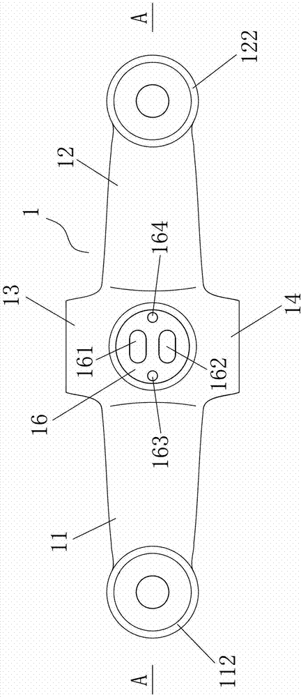
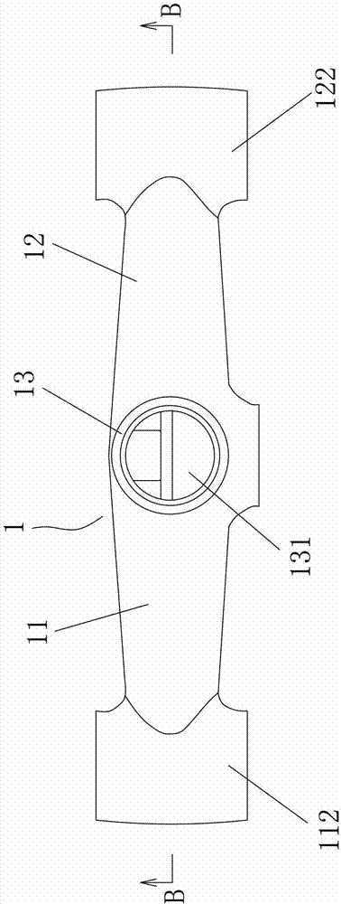
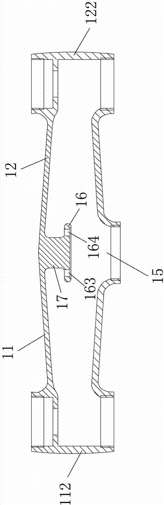
[0017] Figure 1 to Figure 4 As shown, a cold and hot water mixing valve body with upper and lower water outlet channels includes a generally cross-shaped valve housing 1, and the middle of the left arm 11 and right arm 12 of the valve housing 1 is provided with water inlet channels 111, 121, The middle of the upper arm 13 and the lower arm 14 of the valve casing 1 is provided with water outlet passages 131, 141, the joints of the left and right arms 11, 12 and the upper and lower arms 13, 14 are provided with a spool installation passage 15, and the middle of the left arm and the right arm The water inlet channels 111 and 121 are connected through the valve core installation channel 15, the bottom of the valve core installation channel 15 is provided with a valve core positioning partition 16, and a rear partition is connected betwee...


PUM


Abstract

The invention discloses a cold-hot water mixing valve body with an upper water outlet passage and a lower water outlet passage. The cold-hot water mixing valve body comprises a generally cross valve casing. Water inlet passages are arranged in the middle of a left arm of the valve casing and in the middle of a right arm of the valve casing. Separated water outlet passages are arranged in the middle of an upper arm of the valve casing and in the middle of a lower arm of the valve casing. A spool mounting passage is arranged at the connection of the left arm, the right arm, the upper arm and the lower arm. The water inlet passage of the left arm is communicated with the water inlet passage of the right arm through the spool mounting passage. A spool positioning partition is disposed at the bottom of the spool mounting passage. A rear partition is connected between the rear of the spool positioning partition and the valve casing. Through holes for communicating the water outlet passage of the upper arm and the water outlet passage of the lower arm are arranged on the upper side and the lower side of the end face of the spool positioning partition. A spool positioning hole is arranged on each of the left side and the right side of the end face of the spool positioning partition. Lower ends of the left spool positioning hole and the right spool positioning hole are communicated with the water inlet passage of the left arm and the water inlet passage of the right arm respectively. Water can be discharged from the upper water outlet passage and the lower water outlet passage simultaneously by the aid of the cold-hot water mixing valve body which is high in use reliability.

Description

technical field [0001] The invention relates to the technical field of cold and hot water mixing valve manufacturing, in particular to a cold and hot water mixing valve body with upper and lower water outlet channels. Background technique [0002] The common cold and hot water mixing valve body is generally a three-way structure. The middle of the left and right arms of the valve body is the water inlet channel. The middle of the valve body is equipped with a valve core installation channel and a water outlet channel. The water outlet channel is generally used for the nozzle; For example, on September 29, 1993, a patent No. ZL92203004.9 and an invention patent named "multifunctional water mixing valve" were disclosed. The valve body of this water mixing valve is a three-way shape. When the bathtub or bucket under the water mixing valve needs water, the shower nozzle needs to be taken off, causing inconvenience to use. [0003] On the other hand, when installing the spool, a...

Claims


Application Information

Patent Timeline
Patent Type & Authority Applications(China)
IPC IPC(8): F16K27/00
Inventor 曹宏州刘杰峰
Owner LONGYAN HONGHANG SANITARY WARE CO LTD
Why Eureka
Try Eureka