Two-stage bathing wastewater recovery device

A heat recovery device and waste water technology, which is applied in the directions of fluid heaters, lighting and heating equipment, etc., can solve the problems of low heat recovery rate and insufficient utilization of thermal energy of bathing wastewater.

Inactive Publication Date: 2013-01-09
泰安阿拉斯佳空调有限公司
View PDF7 Cites 5 Cited by
  • Summary
  • Abstract
  • Description
  • Claims
  • Application Information

AI Technical Summary

Problems solved by technology

Although this utility model can partially utilize the heat energy in the bathing wastewater, the heat recovery rate is low, and the heat energy of the bathing wastewater is not fully utilized.

Method used


Image

  • Two-stage bathing wastewater recovery device

Examples


Embodiment Construction

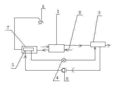
[0011] from figure 1 As can be seen from the structural schematic diagram of the present invention shown, the present invention includes compressor 5, condenser 1, heat exchanger 2, evaporator 3, throttling device 4, heat collecting box 7, shower nozzle 6 and other parts. The input port I of the heat exchanger 2 is connected to the sump for bathing wastewater, the output port I of the heat exchanger 2 is connected to the input port IV of the evaporator 3, the output port IV of the evaporator 3 is connected to the drain port, and the heat exchanger 2 is set In the sump, the sump is arranged below the shower nozzle 6 . A primary heat exchange pipeline is formed between the input port Ⅰ and the output port Ⅰ of the heat exchanger 2, the other input port Ⅱ of the heat exchanger 2 is connected to the tap water pipe 8, and the output port Ⅱ is connected to the heat collection tank 7, and the heat exchanger 2 A primary heat extraction pipeline is formed between the input port II and...


PUM


Abstract

The invention discloses a two-stage bathing wastewater recovery device. An input port I of a heat exchanger is connected with a water collection tank containing bathing wastewater, an output port I of the heat exchanger is connected with an input port IV of an evaporator, an output port IV of the evaporator is connected with a drain outlet, a condenser is mounted in a heat collection case, and the evaporator, a compressor, the condenser and a throttling device form a two-stage heat extraction pipeline. The two-stage bathing wastewater recovery device is high in heat recovery rate, is efficient and energy-saving, safe and reliable, and can be used for houses, units, bath centers and the like.

Description

technical field [0001] The invention relates to a heat recovery device, in particular to a two-stage heat recovery device for bathing wastewater. Background technique [0002] With the continuous improvement of people's quality of life, the proportion of energy consumed by domestic hot water in building energy consumption continues to increase. In conventional bathing systems, the bathing wastewater with high temperature after use is directly discharged into the sewage system, so that all the waste water in the sewage The heat contained above the ambient temperature is wasted, and this loss is more serious for large centralized bathing systems. The actual temperature difference of bathing energy consumption is only about 5°C, and the bathing floor water containing a large amount of heat energy enters the sewer in vain, resulting in the energy consumption of bathing water. is discharged, which contains usable energy at a temperature above the ambient. The temperature of bat...

Claims


Application Information

Patent Timeline
Patent Type & Authority Applications(China)
IPC IPC(8): F24H4/02
Inventor 焦平坤
Owner 泰安阿拉斯佳空调有限公司
Why Eureka
Try Eureka