
Device for recovering waste heat of blast furnace slag by dry granulation and method for recovering waste heat of blast furnace slag

A technology of dry granulation and slag waste heat, which is applied in the field of metallurgy, can solve the problems that the latent heat of slag solidification and high-temperature slag particle sensible heat cannot be utilized, and the additional investment in transportation and power generation equipment increases, so as to achieve short material transportation distance and reduce consumption The effect of high energy consumption and heat recovery rate

Active Publication Date: 2017-05-03
NORTHEASTERN UNIV LIAONING
View PDF4 Cites 4 Cited by
  • Summary
  • Abstract
  • Description
  • Claims
  • Application Information

AI Technical Summary

Problems solved by technology

However, the current existing technology is to granulate in an open environment, and then move the granulated medium and low temperature slag particles to a heat exchanger for waste heat recovery, which will cause the latent heat of slag solidification and the sensible heat of high temperature slag particles to not be utilized
In addition, the recovery and utilization of waste heat from slag particles after granulation is to compress the air after heat exchange, and then transport it to the waste heat boiler for power generation, which will inevitably lead to power consumption required for compressing hot air, heat loss in the transport process, and compression, transport and power generation. Occurrence of additional investment in equipment, etc.

Method used


Image

  • Device for recovering waste heat of blast furnace slag by dry granulation and method for recovering waste heat of blast furnace slag

Examples


Embodiment 1

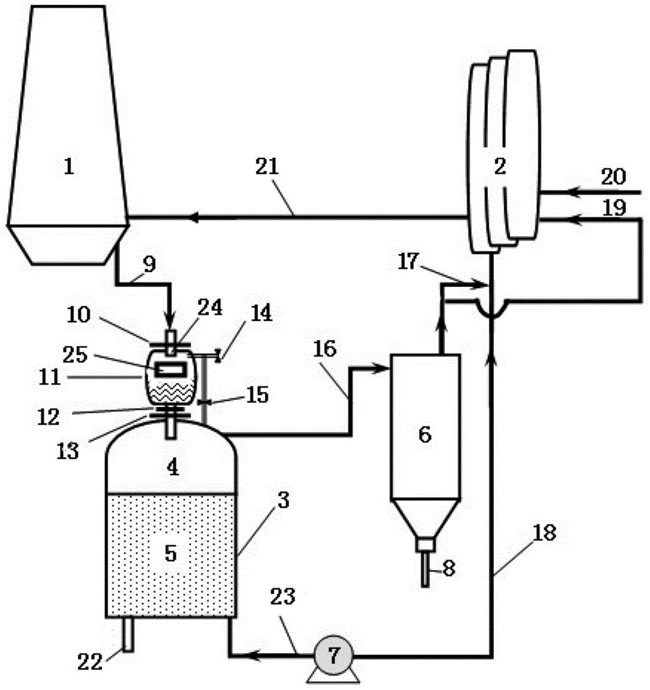
[0037] Refer to attached figure 1 , as an illustrative example of the device and method for recovering waste heat of blast furnace slag by means of dry granulation in the present invention, the relevant content of the present invention will be explained emphatically.

[0038] The system device used in this embodiment is completely consistent with the aforementioned content, and what needs to be added is:

[0039] (1) Install a diverter valve at the outlet of the blower (7), through the diverter valve, a part of the cold air blown by the blower (7) is introduced from the lower part of the granulation kiln (3) through the granulation kiln cold air duct (23) ), the other part is directly supplied to the hot blast stove through the hot blast stove cold air duct (18); Utilization of waste heat within the process.

[0040] (2) Design of granulation kiln. In order to reduce heat loss and maintain structural stability, the materials of the granulation kiln are refractory bricks, he...

Embodiment 2

[0047] It is basically the same as in Example 1, except that: due to insufficient production of blast furnace slag due to production reduction, the converter slag with a temperature of 1650°C produced in the steelmaking process is collected and injected into the slag storage tank for waste heat recovery.


PUM


Abstract

Provided is a device and method for dry granulation recovery of blast furnace slag waste heat, which belongs to the technical field of metallurgical slag heat energy recovery. The device is installed between the blast furnace and the hot blast furnace and consists of a granulating kiln used for dry granulation of blast furnace slag and its accessory piping devices as well as a matching dust collector. Among them, the granulating kiln and its ancillary pipeline devices include: blower, slag introduction tank, upper sealing valve, slag storage tank, sliding water port, lower sealing valve, relief valve, pressure equalizing valve, granulating kiln gas output pipeline, low-temperature granulation Slag discharge pipe, granulating kiln cold air pipe, slag nozzle pipe and granulator. The granulating kiln body is equipped with a granulating area and a heat exchange area. This device can fully recover the latent heat of solidification of molten slag and the sensible heat of high-temperature slag particles. In addition, the hot air generated by waste heat recovery is directly supplied to the blast furnace hot blast stove, which has the advantages of short material transportation distance, low process heat loss, high heat recovery rate, basically no secondary power consumption, and low additional investment.

Description

technical field [0001] The invention belongs to the technical field of metallurgy, in particular to the technical category of heat recovery of blast furnace slag, and specifically relates to a device for recovering waste heat of blast furnace slag by means of dry granulation and a method for recovering waste heat of blast furnace slag by using the device Background technique [0002] As the main by-product of the blast furnace ironmaking process, blast furnace slag is a high-grade silicate secondary resource. At present, the recycling rate of blast furnace slag in major iron-producing countries in the world has reached more than 95%. The main process is to make blast furnace slag into a cement clinker substitute with high added value through water quenching and quenching treatment. However, the traditional water quenching process has disadvantages such as serious consumption of water resources, large emissions of sulfur-containing gases, further dehydration and drying of the...

Claims


Application Information

Patent Timeline
Patent Type & Authority Patents(China)
IPC IPC(8): C21B3/06C21B3/08F27D17/00
CPCY02P10/20Y02P10/25Y02W30/50
Inventor 邵磊孟繁超余珊邹宗树
Owner NORTHEASTERN UNIV LIAONING
Learn More