Fuel cell system

A fuel cell system, fuel cell technology, applied in the direction of fuel cell, fuel cell application, fuel cell integration, etc., can solve the problem of large size of fuel cell system

Inactive Publication Date: 2008-05-14
HONDA MOTOR CO LTD
View PDF1 Cites 5 Cited by
  • Summary
  • Abstract
  • Description
  • Claims
  • Application Information

AI Technical Summary

Problems solved by technology

Therefore, a large amount of heat insulating material etc. is used, so that the size of the fuel cell system becomes considerably large

Method used


Image

  • Fuel cell system
  • Fuel cell system
  • Fuel cell system

Examples


Embodiment Construction

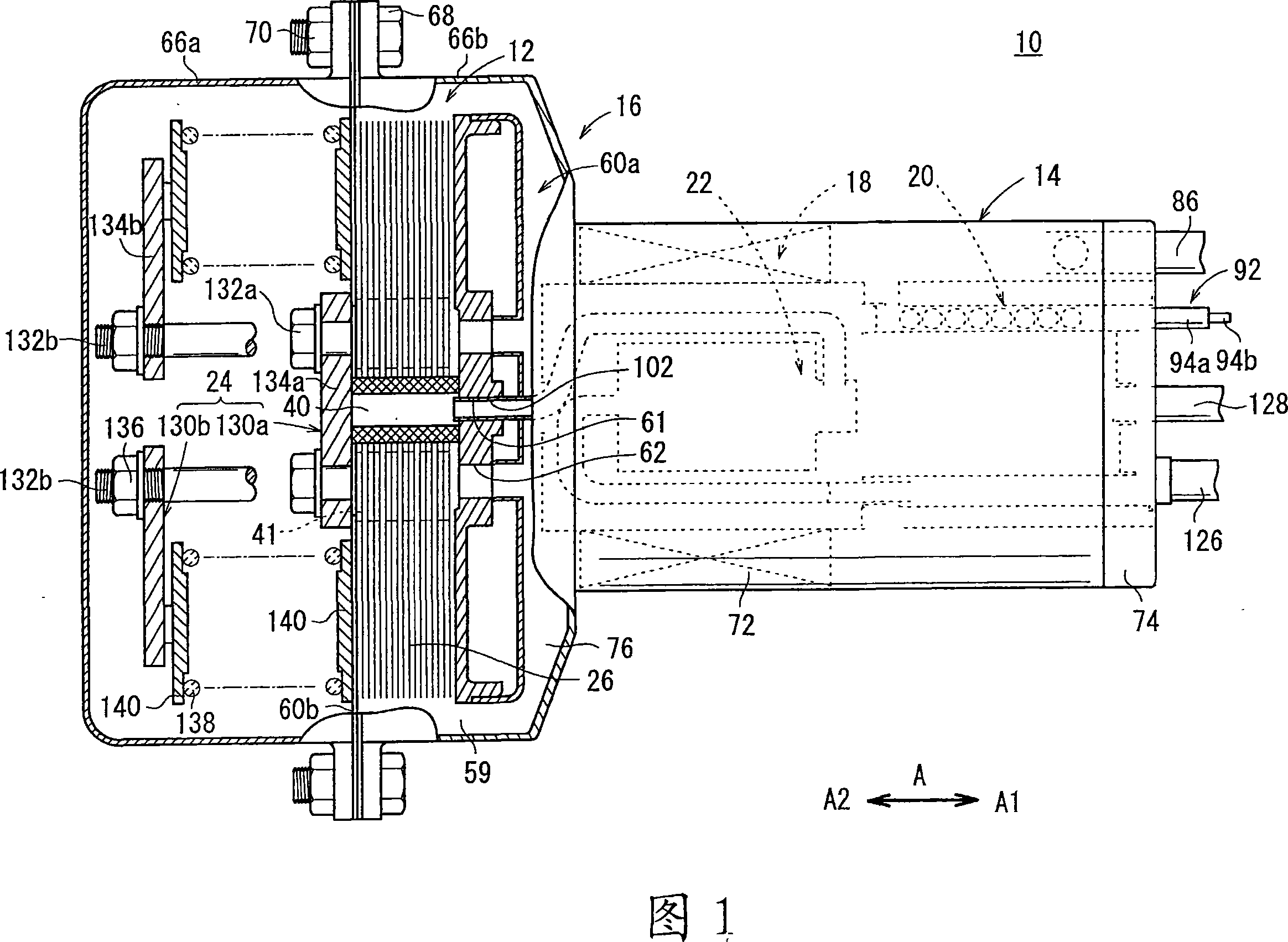
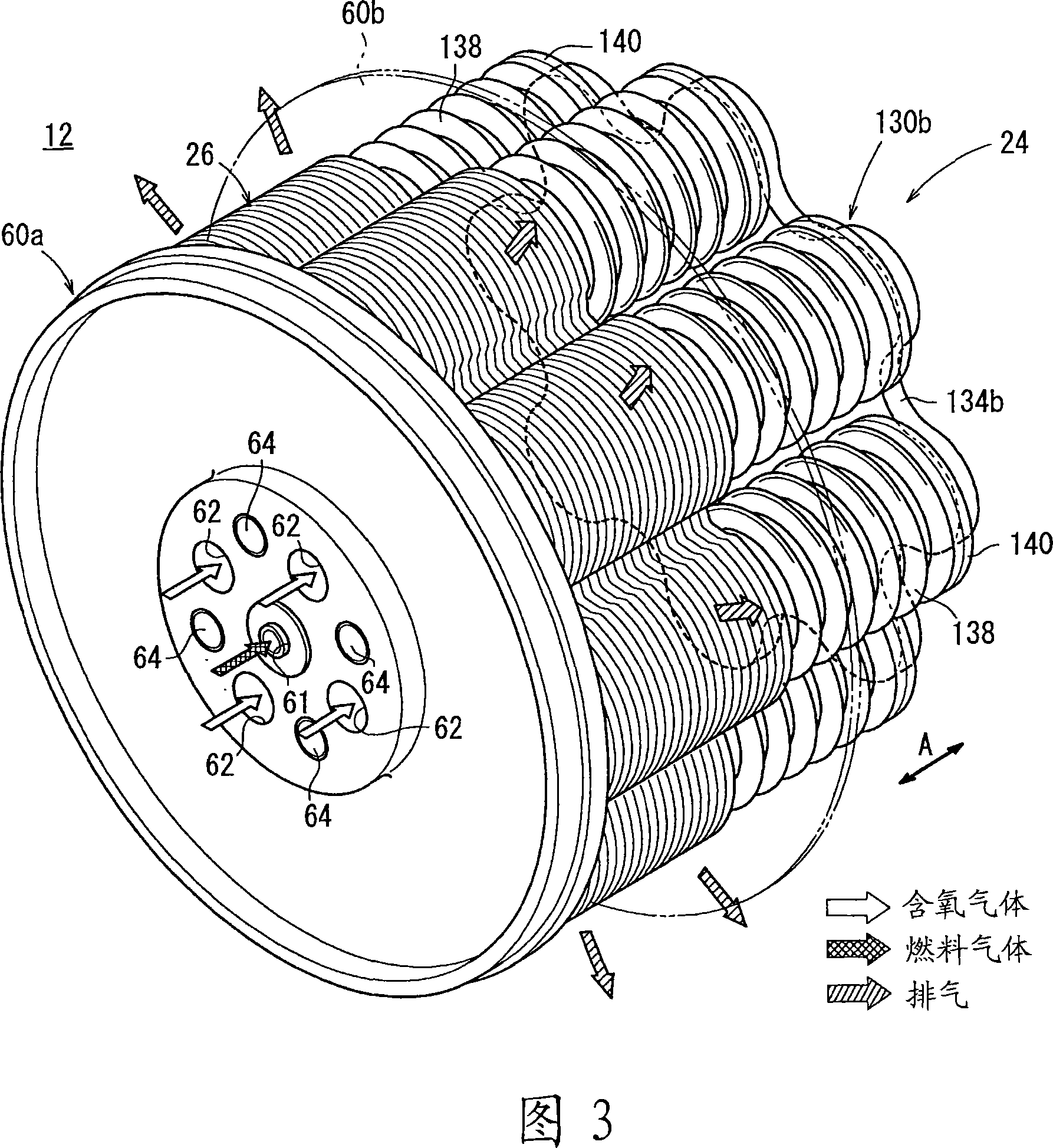
[0027] The fuel cell system 10 is used in a variety of applications, including stationary and mobile applications. For example, the fuel cell system 10 is mounted on a vehicle. As shown in FIG. 1 , the fuel cell system 10 includes a fuel cell stack 12 , a fluid unit 14 disposed on one side of the fuel cell stack 12 , and a case 16 that accommodates the fuel cell stack 12 and the fluid unit 14 .

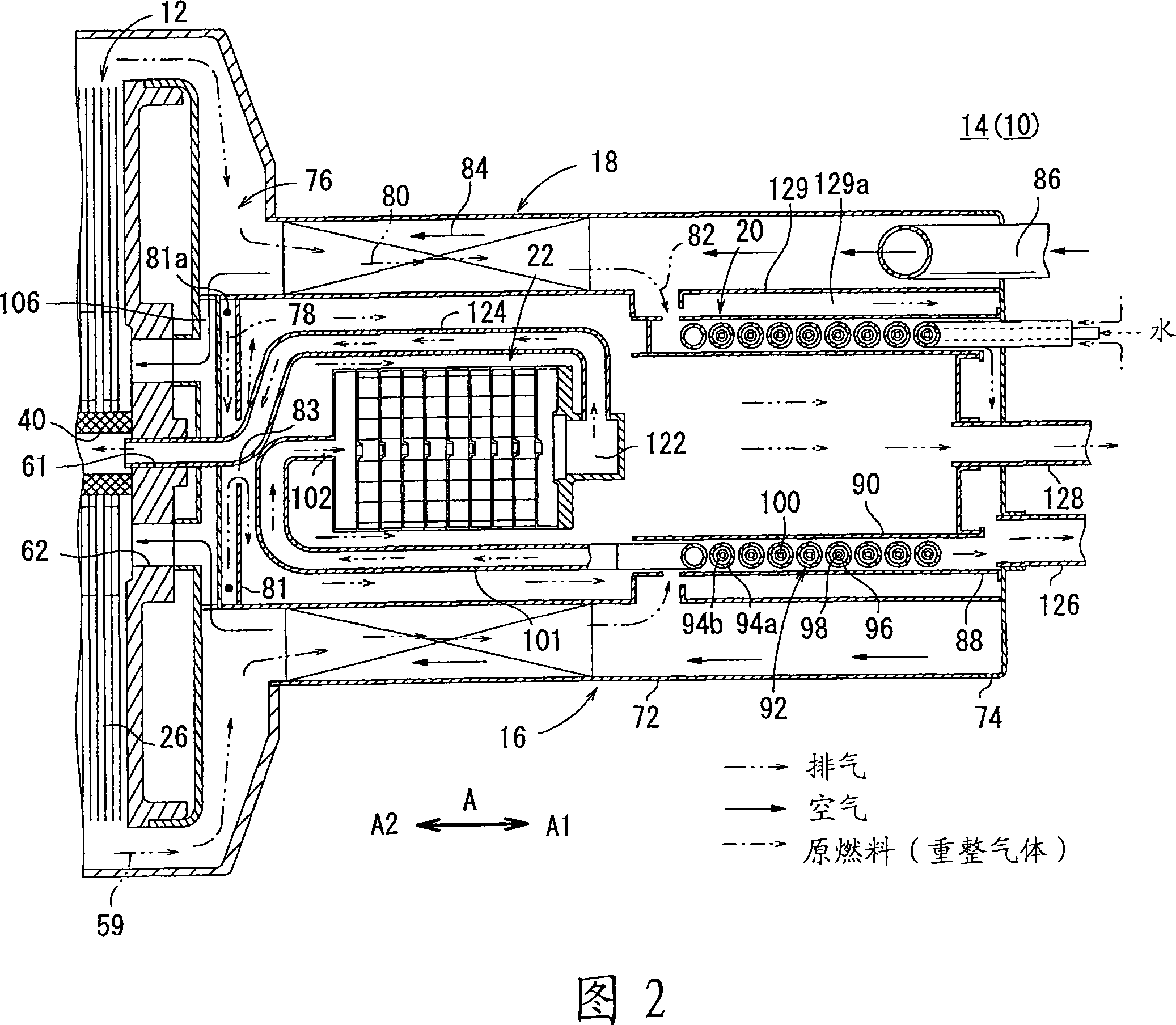
[0028] As shown in FIGS. 1 and 2 , the fluid unit 14 includes a heat exchanger 18 for heating the oxygen-containing gas before it is supplied to the fuel cell stack 12 , for evaporating water to produce a primarily hydrocarbon-containing raw fuel (e.g. , city gas) and steam mixed fuel evaporator 20 and reformer 22 for reforming the mixed fuel to produce reformed gas.

[0029] Reformer 22 is used to use high carbon (C 2+ ) hydrocarbons (such as ethane (C 2 h 6 ), propane (C 3 h 6 ) and butane (C 4 h 10 )) by steam reforming to produce mainly methane (CH 4 ) primary reformer of...


PUM


Abstract

A fluid unit includes a heat exchanger, an evaporator, and a reformer. The fluid unit is provided in a third case unit. In the third case unit, an exhaust gas channel as a passage of an exhaust gas is provided. The exhaust gas channel includes a first channel for supplying the exhaust gas to the reformer, a second channel for supplying the exhaust gas to the heat exchanger, and a third channel connected to the downstream side of the second channel for supplying the exhaust gas to the evaporator. The exhaust gas supplied to the evaporator has the lower temperature due to the heat exchange in the heat exchanger.

Description

technical field [0001] The present invention relates to a fuel cell system, wherein a fuel cell group, a heat exchanger, an evaporator and a reformer are arranged in a housing. Background technique [0002] For example, solid oxide fuel cells (SOFCs) employ electrolytes of ion-conducting oxides such as stabilized zirconia. An electrolyte is interposed between an anode and a cathode to form an electrolyte electrode assembly (unit cell). The electrolyte electrode assembly is interposed between separators (bipolar plates). In use, a predetermined number of unit cells and separators are stacked together to form a fuel cell stack. [0003] Generally, hydrogen gas generated from hydrocarbon-based raw fuel by a reformer is used as fuel gas supplied to a fuel cell. In the reforming plant, after the reformed raw material gas is obtained from hydrocarbon-based raw fuel such as fossil fuel (for example, methane or LNG (liquefied natural gas)), the reformed raw material gas is subjec...

Claims


Application Information

Patent Timeline
Patent Type & Authority Applications(China)
IPC IPC(8): H01M8/06H01M8/24H01M8/04H01M8/12
CPCY02B90/16Y02E60/50C01B2203/066H01M2008/1293H01M8/2475H01M8/0247H01M8/0618H01M2250/405H01M8/04014B01J8/0492B01J2219/2481B01J2208/00309B01J8/0496B01J8/0469B01J2208/0053F28D7/024C01B2203/0811B01J2219/2453B01J2219/247C01B2203/0244Y02E60/525B01J2219/2458B01J19/249C01B2203/0233B01J2208/00504F28D7/0066C01B2203/1288H01M8/248B01J8/0453H01M8/0625C01B3/382B01J2219/2465Y02B90/10Y02P20/10H01M8/04H01M8/06
Inventor 锺尾幸久
Owner HONDA MOTOR CO LTD
Why Eureka
Try Eureka