Yarn drying oven

An oven and yarn technology, applied in the field of yarn ovens and yarn drying equipment, can solve the problems of uncontrollable air dispersion and flow, and achieve convenient baking time, high pass rate, and good baking uniformity

Inactive Publication Date: 2013-01-09
CHANGZHOU POLYACE TEXTILE & YARN
View PDF2 Cites 9 Cited by
  • Summary
  • Abstract
  • Description
  • Claims
  • Application Information

AI Technical Summary

Problems solved by technology

Its air dispersion is completely dependent on the fan, and the air dispersion flow cannot be controlled

Method used


Image

  • Yarn drying oven
  • Yarn drying oven
  • Yarn drying oven

Examples


Embodiment

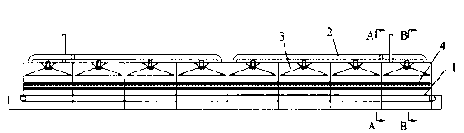
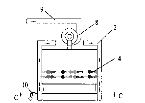
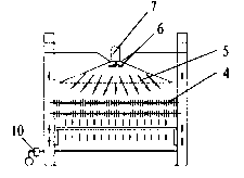
[0018] like Figure 1 to Figure 4 Shown, a kind of yarn oven comprises drying chamber 3, conveyer belt 1, heat exchanger 4, air collecting pipe 2, blower fan 8 and exhaust pipe 9, and drying chamber 3 is composed of a plurality of connected drying chambers Unit 3-1 is composed. The heat exchanger 4 is a finned heat exchanger, and steam is used as a heat source during operation. The conveyor belt 1 is located at the lower part of the yarn oven and passes through the drying chamber 3 , and the heat exchanger 4 is arranged at the upper part of the conveyor belt 1 and is located in the drying chamber 3 . The air collecting pipe 2 is located at both sides of the drying chamber 3, and the air collecting pipe 2 is connected with the exhaust pipe 9 through the fan 8 on the top of the drying chamber 3, and the outlet of the fan 8 is connected with the exhaust pipe 9. The blower fan 8 can be turned on according to actual needs, so as to facilitate the control of the drying effect. Th...


PUM


Abstract

The invention relates to yarn drying equipment, in particular to a yarn drying oven. The yarn drying oven comprises a drying chamber (3), a conveying belt (1), a heat exchanger (4), an air collection pipe (2), a fan (8) and an air exhaust pipe (9), wherein the conveying belt (1) is positioned at the lower part of the yarn drying oven and penetrates through the drying chamber (3); the heat exchanger (4) is arranged at the upper part of the conveying belt (1) and is positioned in the drying chamber (3); the air collection pipe (2) is positioned at the two sides of the drying chamber (3) and is connected with the air exhaust pipe (9) through the fan (8) at the upper part of the drying chamber (3); a dispersion cover (5), an impeller (6) and a motor (7) which is used for driving the impeller (6) are arranged at the upper part of the drying chamber (3); and the impeller (6) is positioned below the dispersion cover (5) and the motor (7) is positioned above the dispersion cover (5). The yarn drying oven is simple in structure, can uniformly distribute dry air and has good yarn baking effect, good yarn baking uniformity and good quality of baked yarns.

Description

technical field [0001] The invention relates to a yarn drying device, in particular to a yarn oven. The invention is mainly applicable to steam heating and drying of yarn, and the invention belongs to the technical field of drying equipment. Background technique [0002] In the yarn printing and dyeing process, the yarn needs to be baked through the yarn oven, and the yarn must meet the specified baking requirements to be used in the subsequent process. [0003] Chinese Patent Publication No. CN201417067Y discloses a mesh belt dryer, which consists of a chassis, a conveying mesh belt, a rotating shaft, a heating valve, a drying chamber, a finned spiral heat exchanger, a control box and a heating probe. When working, the product enters the drying box with the conveying mesh belt, and the stability in the drying box is produced by the finned spiral heat exchanger. Its air distribution relies on prefabricated air volume distributors with limited adjustment capabilities. [...

Claims


Application Information

Patent Timeline
Patent Type & Authority Applications(China)
IPC IPC(8): F26B13/10F26B21/00F26B25/06F26B25/00D06B15/00
Inventor 罗坚平
Owner CHANGZHOU POLYACE TEXTILE & YARN
Why Eureka
Try Eureka