Clamping device for pipe-flat plate line contact fretting wear experiments

A technology of fretting wear and clamping devices, which is applied in the direction of measuring devices, instruments, scientific instruments, etc., can solve the problems of high cost of biaxial fretting wear testing machines, and achieve the effects of reducing experimental costs, convenient operation, and simple structure

Active Publication Date: 2013-01-09
SUZHOU NUCLEAR POWER RES INST +1
View PDF5 Cites 29 Cited by
  • Summary
  • Abstract
  • Description
  • Claims
  • Application Information

AI Technical Summary

Problems solved by technology

In the prior art, the cost of the biaxial fretting wear testin...

Method used


Image

  • Clamping device for pipe-flat plate line contact fretting wear experiments

Examples


Embodiment Construction

[0022] The technical solutions of the present invention will be further described below in conjunction with the accompanying drawings and specific embodiments.

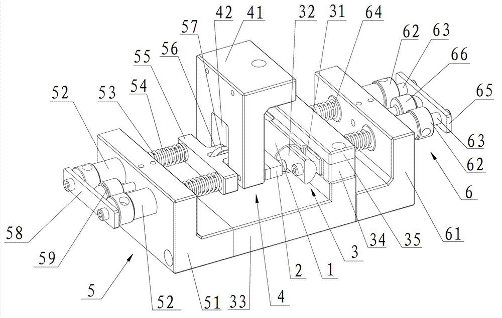
[0023] see figure 1 The shown clamping device for the tube-flat line contact fretting wear test is set on the testing machine for clamping the cylindrical tube 1 and the flat plate 2 in the tube-plate line contact fretting wear test, where The testing machine is an ordinary uniaxial fatigue testing machine. The cylindrical tube 1 and the flat plate 2 both extend along the horizontal front-back direction on the clamping device. The front-back direction here refers to the observation by the observer. figure 1 The front and rear direction of the line of sight, correspondingly, the horizontal left and right direction refers to the observer's observation figure 1 Time figure 1 in the left-right direction. The clamping device includes a cylindrical tube clamping assembly 3 for clamping the cylindrical tube 1 ,...


PUM


Abstract

The invention discloses a clamping device for pipe-flat plate line contact fretting wear experiments. In the clamping device, a cylindrical pipe clamping assembly and a flat plate clamping assembly are arranged to stably clamp experimental samples i.e., a cylindrical pipe and a flat plate respectively; a cylindrical pipe pressing assembly and a flat plate pressing assembly are arranged to respectively provide pressing forces along horizontal opposite directions for the cylindrical pipe and the flat plate, and therefore, the flat plate and the cylindrical pipe are in line contact and bear stable and uniform normal load and the pipe-flat plate line contact fretting wear experiments can be carried out in cooperation with a uniaxial fatigue testing machine. The clamping device is simple in structure, convenient for operation, capable of carrying out the experiments in cooperation with the conventional uniaxial fatigue testing machine, has no need for introducing a biaxial fretting wear testing machine, thereby reducing the experimental cost.

Description

[0001] technical field [0002] The invention relates to a clamping device for a tube-flat line contact fretting wear experiment. [0003] Background technique [0004] At present, the laboratory mostly adopts the ball-plane point contact method when conducting fretting wear experiments in the laboratory, but the experimental research on the fretting wear problem of the cylinder-plane line contact method that often occurs in engineering practice is relatively difficult, mainly because the testing machine The design needs to consider three aspects of technical issues: (1) ensure that the two contact bodies are in full contact within the length range; (2) ensure that the normal load is applied quantitatively; (3) ensure that the relative slip of the two contact bodies is controllable within a certain range . In the prior art, the cost of a biaxial fretting wear testing machine capable of realizing the above functions is relatively high. In order to reduce the cost of the e...

Claims


Application Information

Patent Timeline
IPC IPC(8): G01N3/04
Inventor 梅金娜王兆希黄磊张国栋薛飞遆文新林磊
Owner SUZHOU NUCLEAR POWER RES INST
Why Eureka
Try Eureka