Electric drive unit

An electric drive unit, the technology of the drive unit, applied in the direction of electric components, electrical components, connection with control/drive circuits, etc., can solve the problem of necessary cooling, and achieve the effect of low additional cost, simple and compact structure

Active Publication Date: 2013-01-09
MAGNA POWERTRAIN AG & CO KG
View PDF10 Cites 12 Cited by
  • Summary
  • Abstract
  • Description
  • Claims
  • Application Information

AI Technical Summary

Problems solved by technology

In addition, the transmission

Method used


Image

  • Electric drive unit

Examples


Embodiment Construction

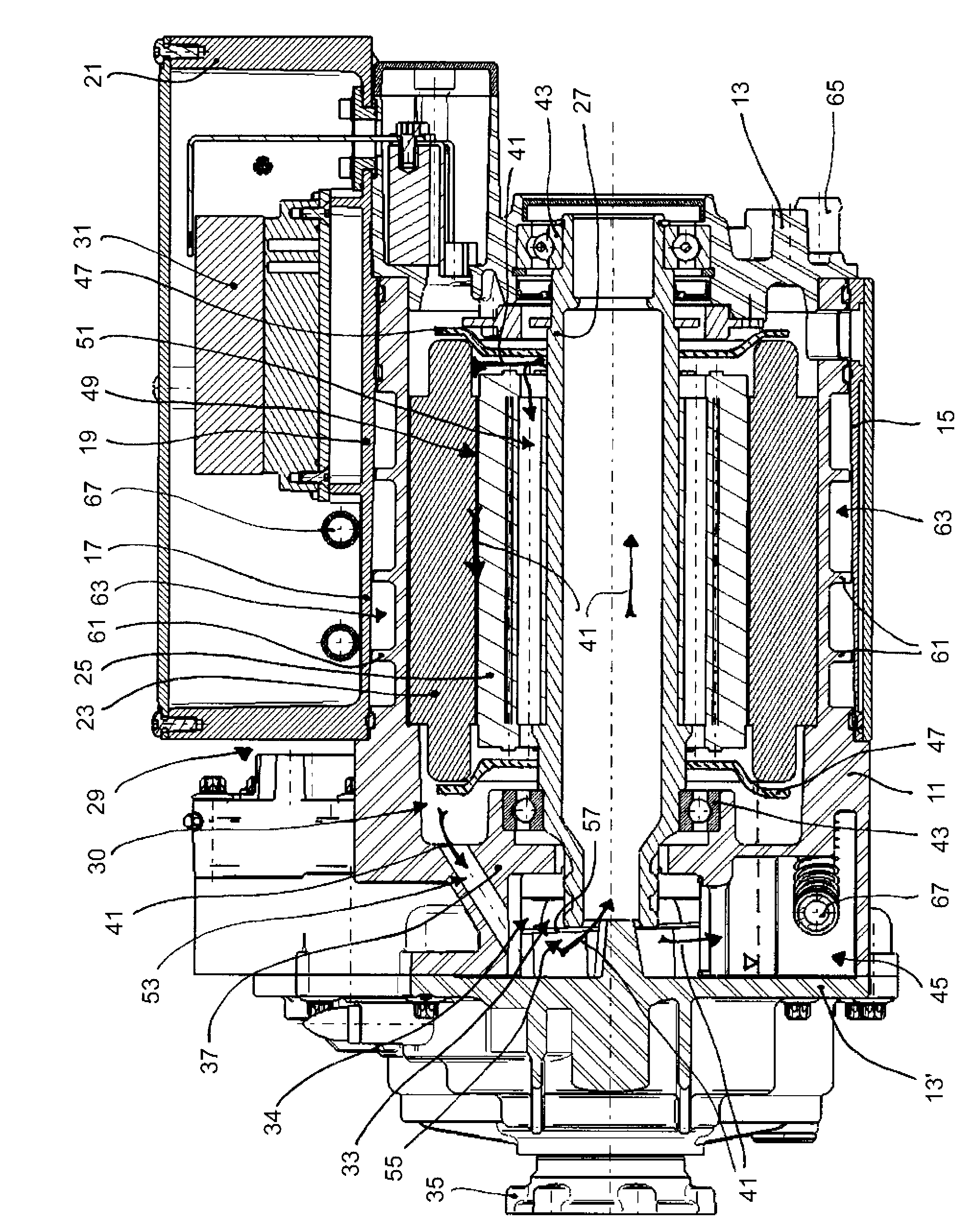
[0023] The electric drive unit shown comprises a metal housing 11 which is closed at its two end sides by housing covers 13 , 13 ′ in each case. The metal shell 11 is preferably cast from aluminum. Furthermore, the electric drive unit has a plastic housing 15 with a cylindrical outer surface 17 , which surrounds a cylindrical outer surface 19 of the metal housing 11 on all sides. Furthermore, the plastic housing 15 has a cuboid circuit housing section 21 mounted on the upper side.

[0024] Inside the outer peripheral surface 19 , the stator 23 is inserted, for example pressed, into the metal shell 11 . Arranged within the stator 23 is a rotor 25 which is connected in a rotationally fixed manner to a hollow output shaft 27 which is rotatably mounted in the metal housing 11 . The stator 23 and the rotor 25 form a motor 29 , in particular a three-phase asynchronous motor. The motor 29 is provided in the engine room 30 of the metal case 11 . A circuit including, for example, a...


PUM


Abstract

The invention relates to an electric drive unit comprising an electric motor having a stator and a rotor, a transmission, an electric circuit, and a housing. The housing forms a motor compartment in which the electric motor is disposed, and a transmission compartment in which at least part of the transmission is disposed. The drive unit comprises a lubricating circuit in which a lubricating fluid for lubricating and cooling the rotor of the electrical machine and the transmission is carried, wherein the lubricating fluid circulates between the motor compartment and the transmission compartment. The drive unit further comprises a cooling circuit, in which a coolant is carried for cooling the stator of the electric motor and the electric circuit. The coolant of the cooling circuit has a heat exchanging connection to the lubricating fluid of the lubricating circuit.

Description

technical field [0001] The invention relates to an electric drive unit, which is used, for example, as a drive source on one of the axles in an electric or electric hybrid motor vehicle. The drive unit includes an electric motor with a stator and a rotor rotatable inside the stator. The motor can be, for example, a three-phase asynchronous motor. The drive unit also includes a transmission coupled on the inlet side to the output of the electric machine. The transmission can be, for example, a reduction gear and / or an axle differential transmission. Furthermore, the drive unit comprises an electrical circuit, wherein the electrical circuit is, for example, a switched-mode power supply for the electric motor, in particular an inverter. Furthermore, the drive unit comprises a housing forming an engine compartment and a transmission compartment, wherein the electric machine is arranged in the engine compartment and the transmission is at least partially arranged in the transmis...

Claims


Application Information

Patent Timeline
IPC IPC(8): H02K7/116H02K9/19H02K11/04
CPCH02K9/19H02K7/116H02K11/0073H02K5/20H02K11/33H02K5/203
Inventor R.霍夫科克纳D.普里克斯
Owner MAGNA POWERTRAIN AG & CO KG
Why Eureka
Try Eureka