
Aquatic water aerator

An aeration device and a technology for aquaculture water, applied in water aeration, fish farming, degassed water/sewage treatment, etc., can solve problems such as inability to effectively remove carbon dioxide, difficulty in obtaining pure oxygen, uneven bubbles, etc., and achieve reduction The effect of water circulation rate, improvement of water quality in aquaculture pond, and good pushing effect

Inactive Publication Date: 2014-04-16
FISHERY MACHINERY & INSTR RES INST CHINESE ACADEMY OF FISHERY SCI
View PDF7 Cites 0 Cited by
  • Summary
  • Abstract
  • Description
  • Claims
  • Application Information

AI Technical Summary

Problems solved by technology

[0005] 1. In production practice, many aquaculture farms in remote areas have few oxygen-making factories and it is difficult to obtain pure oxygen, which seriously restricts the development of high-density industrial aquaculture in the local area
[0006] 2. The traditional blower aeration device generally aerates the fish pond air through aeration stones and microporous aeration discs. The former has disadvantages such as large bubbles, uneven bubbles, and short air-water contact time, resulting in low oxygen utilization rate; The latter has the disadvantages of large pressure loss, uneven air distribution, easy blockage, and easy damage.
[0007] 3. A set of special oxygen production and aeration equipment is required, and the sealing of the whole set of equipment is very high. If there is equipment failure or pipeline damage, pure oxygen will leak, which will easily lead to production accidents
[0008] 4. With the increase of breeding density, the concentration of carbon dioxide emitted by the respiration of farmed animals will continue to accumulate. On the one hand, it will cause breathing difficulties for farmed animals. At the same time, carbon dioxide will affect the dissolution efficiency of oxygen through changes in the partial pressure of water. Methods cannot effectively remove carbon dioxide in aquaculture water

Method used


Image

  • Aquatic water aerator
  • Aquatic water aerator
  • Aquatic water aerator

Examples


Embodiment Construction

[0039] The present invention will be further described below in conjunction with accompanying drawing.

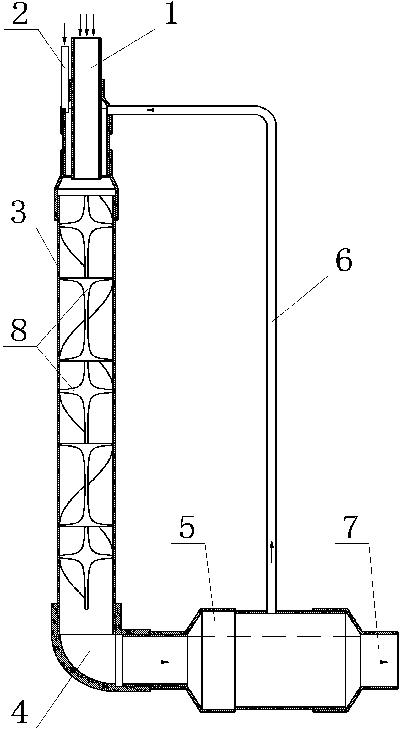
[0040] figure 1 Among them, the pressurized water inlet pipe 1 and the compressed air inlet pipe 2 are inserted into the gas-liquid mixing pipe 3 axially along the vertically arranged gas-liquid mixing pipe 3 respectively, and communicate with the upper end of the inner chamber of the gas-liquid mixing pipe 3 .

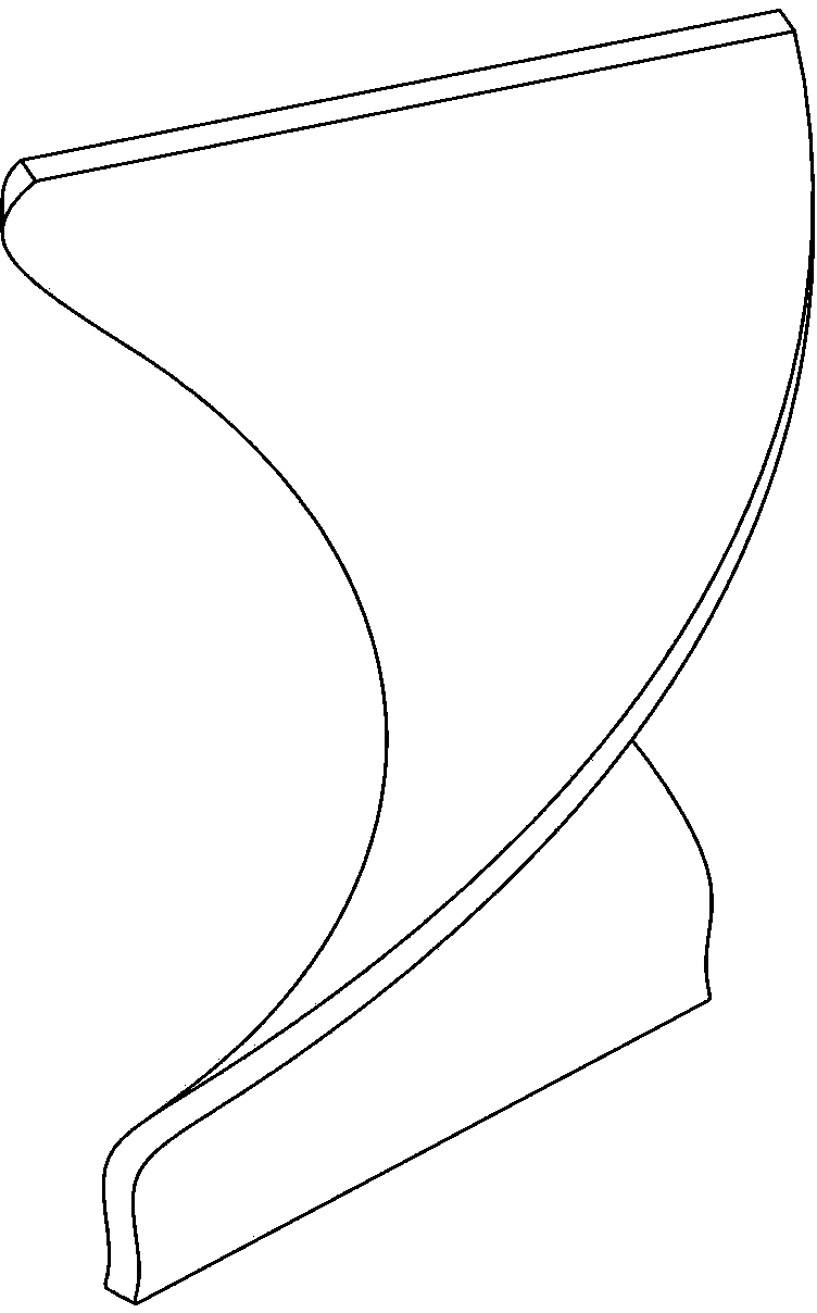
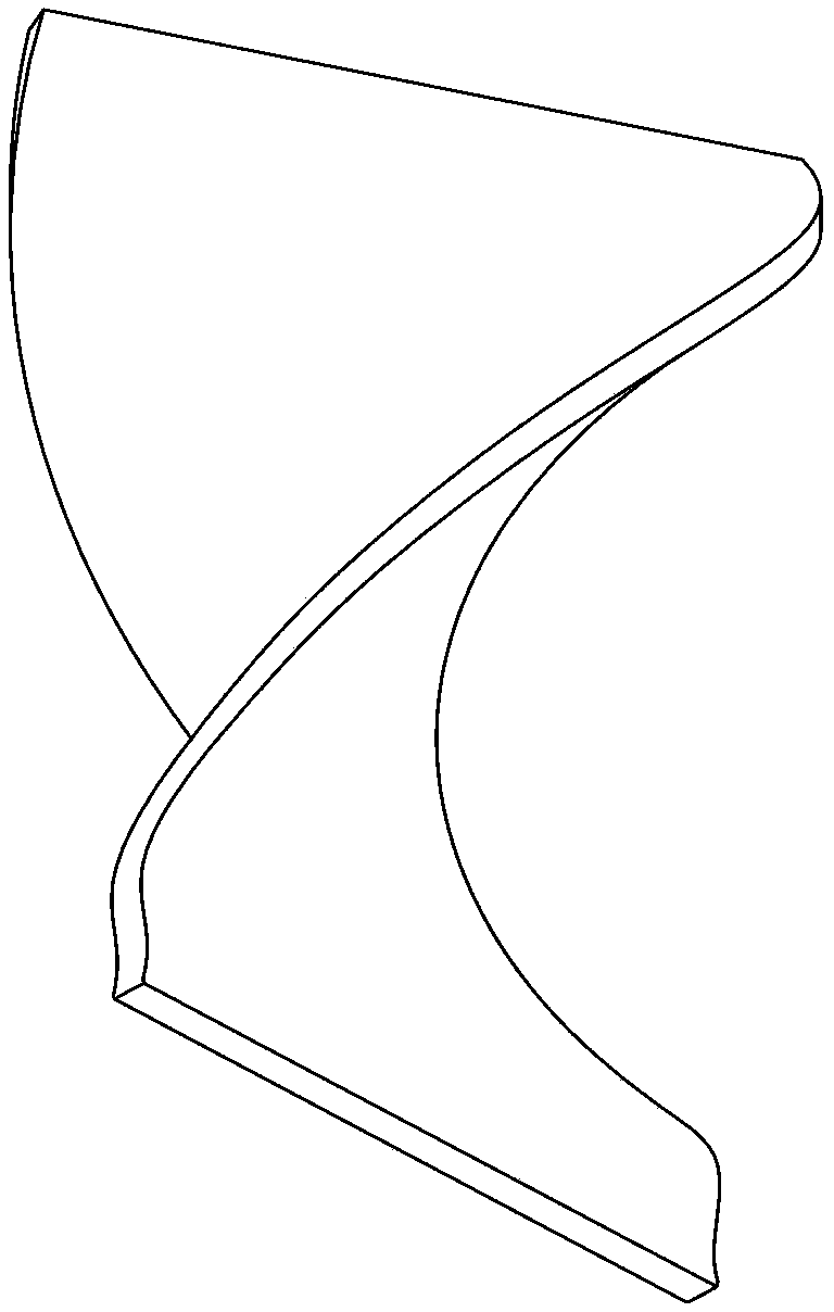
[0041] The inner chamber of the gas-liquid mixing pipe 3 is in the shape of a circular tube. In the gas-liquid mixing pipe 3 below the pressure water inlet pipe 1 and the compressed air inlet pipe 2, five helical blades 8 are stacked up and down. The helical blades 8 are fixed on the gas-liquid mixing pipe 3. In the mixing tube 3, each helical blade 8 is formed by twisting the upper and lower sides of a flat blade in reverse, the twist angle is 180-360 degrees, and the outer edge of the helical blade 8 matches the inner cavity of the gas-liquid mixing tube 3, The ...


PUM

PropertyMeasurementUnit
angleaaaaaaaaaa

Abstract

Disclosed is an aquatic water aerator. A pressured water inflow pipe and a compressed air inflow pipe are respectively inserted into an air-liquid mixing pipe axially along the vertical air-liquid mixing pipe and are communicated with the upper end of an inner cavity of the air-liquid mixing pipe. The inner cavity of the air-liquid mixing pipe is a tubular cavity provided with a plurality of spiral blades inside. The lower end of the inner cavity of the air-liquid mixing pipe is communicated with one end of the inner cavity of an air-liquid separating pipe. The inner cavity of the air-liquid separating pipe is a transverse tubular cavity. The top of the inner cavity of the air-liquid separating pipe is communicated with the inner cavity of the air-liquid mixing pipe through a gas recovery pipe. The other end of the inner cavity of the air-liquid separating pipe is communicated with an aerating water outflow pipe. The air-liquid separating pipe is larger than the air-liquid mixing pipe, the aerating water outflow pipe and a bend in inner diameter. The pressure of pressured water in the pressured water inflow pipe is larger than that of compressed air in the compressed air inflow pipe. The aquatic water aerator without any mechanical device supplies oxygen and water to aquatic waters by efficiently dissolving oxygen in compressed air by pressured water, and is simple in structure and low in cost.

Description

technical field [0001] The invention relates to the field of aquaculture, in particular to an oxygen-increasing aeration device for aquaculture water. Background technique [0002] In the field of aquaculture, the main function of the aeration device is to provide sufficient oxygen for the farmed animals and promote the healthy growth of the farmed animals. There are two types of existing aeration devices: one is blast aeration device, which is further divided into macroporous aeration device, mesopore aeration device, small pore aeration device and microporous aeration device; the other is mechanical aeration device. The surface aeration device usually uses the impeller and blades to rotate and hit the water surface to achieve the purpose of increasing oxygen. The latter has high energy consumption and is not suitable for indoor factory farming. Therefore, the blast aeration device is usually used at present. [0003] With the gradual development of the aquaculture indus...

Claims


Application Information

Patent Timeline
Patent Type & Authority Patents(China)
IPC IPC(8): A01K63/04C02F1/20C02F7/00
CPCY02W10/10
Inventor 宋奔奔吴凡单建军宿墨刘鹏
Owner FISHERY MACHINERY & INSTR RES INST CHINESE ACADEMY OF FISHERY SCI
Learn More