Scroll compressor

A scroll compressor and compression mechanism technology, applied in the field of scroll compressors, can solve the problems of pressure deviation of relief valve, difficult relief valve, change of spring pressing force, etc., so as to suppress deformation or impact sound and improve performance and reliability effects

Active Publication Date: 2013-01-16
HITACHI JOHNSON CONTROLS AIR CONDITIONING INC
View PDF8 Cites 12 Cited by
  • Summary
  • Abstract
  • Description
  • Claims
  • Application Information

AI Technical Summary

Problems solved by technology

[0013] In the relief valve device of the scroll compressor disclosed in Patent Document 1, since the bush is press-fitted into the bush press-fitting portion, compressive stress is generated on the fixed scroll, and deformation of the fixed scroll toward the wrap side occurs. , has issues with reliability and performance
In addition, the pressing force of the spring varies due to variations in the depth accuracy of the bushing press-fitting part, and variations in the positional accuracy of the bushing press-fitting.
Therefore, the pressure at which the relief valve opens has a large deviation, and it is difficult to obtain a stable relief valve function in batch production
[0014] In the relief valve device of the scroll compressor disclosed in Patent Document 2, since the valve pressing body is free when the relief valve closes the relief flow path, vertical movement of the valve pressing body at the guide portion is likely to occur.
As a result, there is a collision sound between the retainer and the valve pressing body, and there is also a problem that the retainer or the valve pressing body is deformed due to the collision, resulting in insufficient strength and reduced reliability.

Method used


Image

  • Scroll compressor
  • Scroll compressor
  • Scroll compressor

Examples


Embodiment Construction

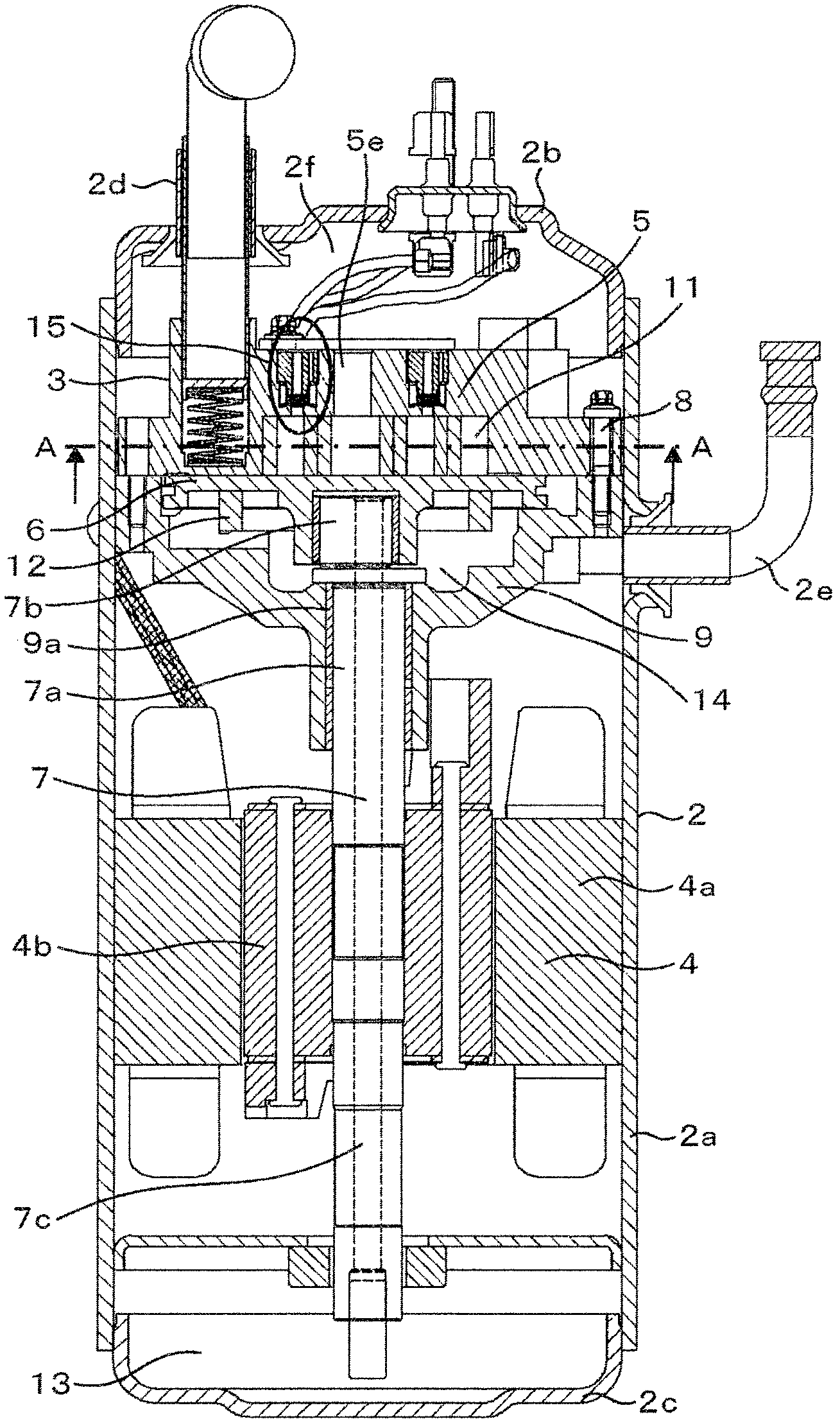
[0072] Below, use Figure 1 ~ Figure 7 The embodiments of the present invention will be described. figure 1 It is a cross-sectional view of the vertical scroll compressor 1. Inside the airtight container 2 of the scroll compressor 1, there are: an electric motor 4; a scroll compression mechanism 3, which is configured by meshing a fixed scroll 5 with an orbiting scroll 6 driven by the electric motor 4, and compresses the refrigerant The European-style ring 12 as a rotation restricting member supports and guides the orbiting scroll 6 between the fixed scroll 5 and the frame 9 so that the orbiting motion relative to the fixed scroll 5 does not rotate.

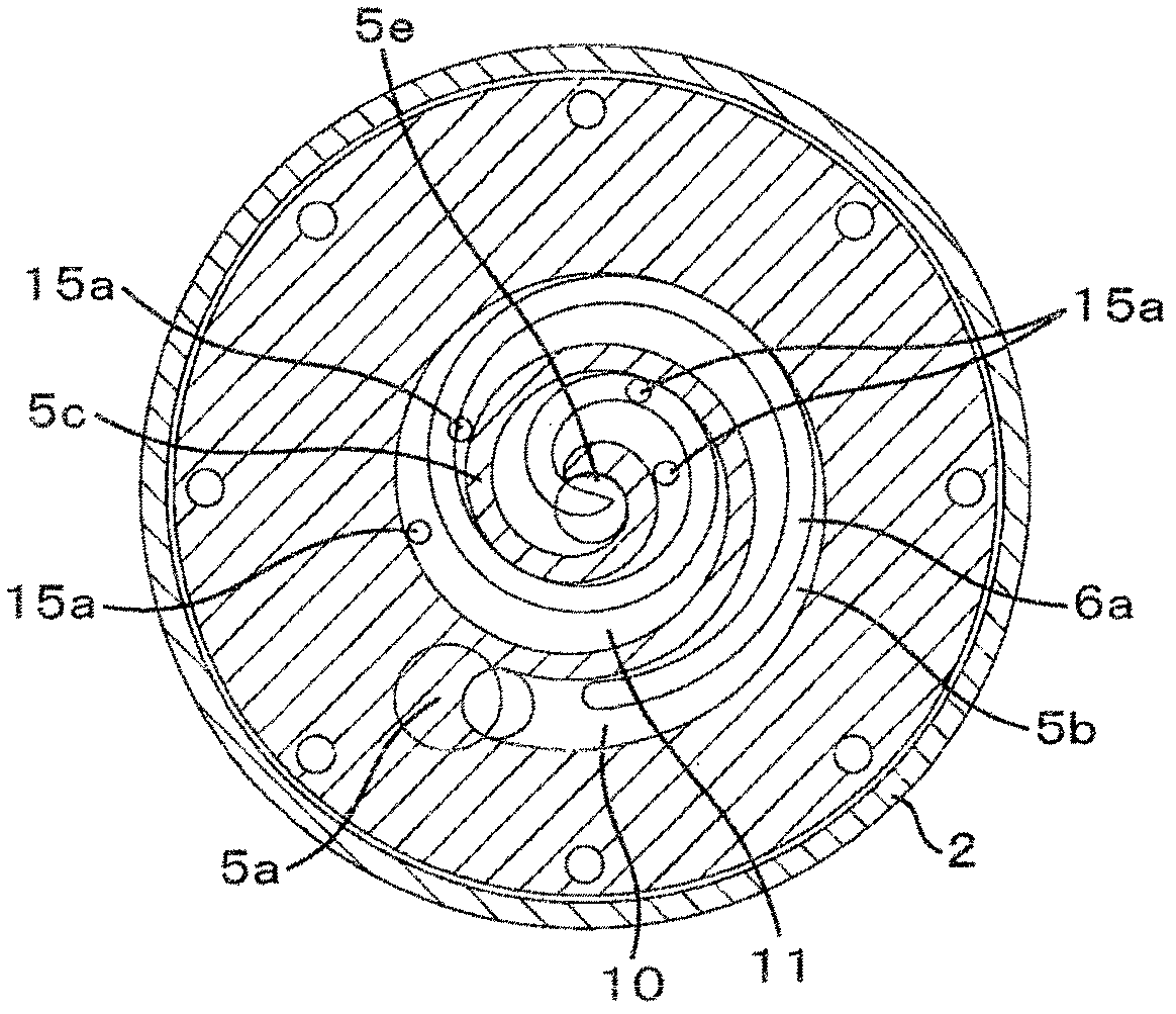
[0073] figure 2 Yes figure 1 A cross-sectional view of the compression mechanism along the line A-A. The orbiting scroll 6 receives the rotation of the electric motor 4 via the crankshaft 7 and is driven to orbit while being restricted by the Euro ring 12. The refrigerant gas sucked in from the suction port 5a is compressed and di...


PUM


Abstract

Subject of the present invention is to provide a vortex compressor, which can inhibit by setting the overflow valve pressure of valve gear body pressure into the cause of fixed vortex plate deformation, and the inhibition caused by collision of retainer and valve pressure deformation of the body or a collision. Fixed vortex dish with overflow valve device, the pressure of compression chamber rises above to set pressure, open flow so that the compression chamber and pressure chamber connected from the overflow valve device is connected the overflow of the compression chamber and jet pressure chamber flow, overflow valve open and close the overflow flow, configuration between the relief valve and the retainer and the elasticity of the overflow valve is given according to the pressure of the valve pressure, limiting valve pressure of the moving range of retainer, the overflow valve closed state of the overflow mouth and open the overflow state of flow in any conditions, all press pressure the valve pressure by elastic body pressure against the retaining ring.

Description

Technical field [0001] The present invention relates to a scroll compressor used in refrigeration and air conditioning equipment and the like. Background technique [0002] Scroll compressors used in indoor air conditioners and the like are used under a wide range of operating conditions, so it is inevitable to operate in a state of overcompression of refrigerant gas or liquid compression of refrigerant and refrigerating machine oil. Therefore, a scroll compressor with a structure that can withstand the above-mentioned situation is required. [0003] Patent Document 1 discloses a conventional scroll compressor that prevents overcompression or liquid compression. Hereinafter, the scroll compressor of Patent Document 1 will be described. A discharge pressure chamber is formed in a closed container having a suction port and a discharge port. The electric motor and the compression mechanism are housed in the discharge pressure chamber. In the compression mechanism, a fixed scroll h...

Claims


Application Information

Patent Timeline
Patent Type & Authority Applications(China)
IPC IPC(8): F04C18/02F04C29/00
Inventor 村上晃启高野龙扶岛田敦
Owner HITACHI JOHNSON CONTROLS AIR CONDITIONING INC
Why Eureka
Try Eureka