Variable-diameter crankshaft type gear stepless speed change method and speed changer

A technology of continuously variable speed and crankshaft, which is applied in the direction of belt/chain/gear, mechanical equipment, transmission device, etc., and can solve the problems of maximum torque, transmission power limitation, slow response of speed change belt, slipping, etc.

Inactive Publication Date: 2013-01-16
杨建明
View PDF6 Cites 4 Cited by
  • Summary
  • Abstract
  • Description
  • Claims
  • Application Information

AI Technical Summary

Problems solved by technology

[0004] The invention discloses a variable-diameter crankshaft-type gear stepless speed change method, which solves the slow response of the speed change belt and the phenomenon of "slipping" when the convent

Method used


Image

  • Variable-diameter crankshaft type gear stepless speed change method and speed changer
  • Variable-diameter crankshaft type gear stepless speed change method and speed changer

Examples


Embodiment 1

[0018] A variable-diameter slider is set on the end face of the power input shaft to form a friction pair on the end face. The variable-diameter slider is coaxial with the planetary gear of the planetary gear train. By controlling the displacement of the axis line of the variable-diameter slider and the axis line of the power input, a The radius of the crankshaft, through the input power of the power input shaft, drives the variable-diameter slider to rotate, so that the axis of the variable-diameter slider rotates around the axis centerline of the power input shaft to form the crankshaft motion; the crankshaft passing through the axis of the variable-diameter slider The motion drives the rotation of the planetary gears of the planetary gear train, and under the limit action of the ring gear of the planetary gear train, the planetary gears transmit the power of the variable diameter slider to the output shaft, realizing the continuous stepless speed change function.

Embodiment 2

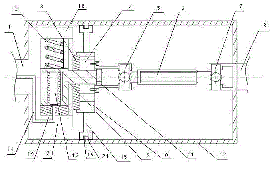
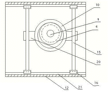
[0020] according to figure 1 As shown, the present invention mainly consists of a power output shaft 1, a return spring 2, a planetary gear follower plate 3, a planetary gear 4, a first universal joint 5, a rotating shaft 6, a second universal joint 7, and a power output shaft 8 , reducing slider 9, follower ring gear 10, box body 12, plunger 13, guide rail 15, chute 16, oil pump top plate 17, spring top plate 18, plunger pump 19, guide sleeve 20, slide rail 21, etc. Wherein, the end face of the power input shaft 1 and the end face of the variable diameter slider 9 are fixedly connected through the spring top plate 18 and the oil pump top plate 17 to form an end face friction pair, and a plunger pump 19 is arranged between the spring top plate 18 and the oil pump top plate 17. Diameter slider 9 is sleeved on the plunger 13 of plunger pump 19 and can move radially. The top of variable diameter slider 9 is connected with return spring 2 to control the displacement of variable d...


PUM


Abstract

The invention discloses a variable-diameter crankshaft type gear stepless speed change method and a speed changer. A variable-diameter slider is arranged on the end face of a power input shaft to form an end face friction pair, the variable-diameter slider and a planetary gear of a planetary gear train are coaxial, a crankshaft radius is formed by controlling the axis of the variable-diameter slider and the axis of the power input shaft, and the power input shaft inputs power to drive the variable-diameter slider to rotate and enable the axis of the variable-diameter slider to rotate around the center line of the power input shaft to form crankshaft movement. The planetary gear of the planetary gear train is driven to rotate by means of the crankshaft movement of the center line of the power input shaft, and power of the center line of the variable-diameter slider is transferred to an output shaft by the planetary gear under the limiting action of a gear ring of the planetary gear train to realize a function of continuous stepless speed change. Gear normally meshed shaft transmission is adopted for realizing continuous variable speed change, the speed change range is wide, the speed ratio ranges from zero to a fixed value, using a clutch for starting is not needed, large torque is available while 'skidding' is avoided, the speed change response is quick, and transmission efficiency is free of fluctuation.

Description

technical field [0001] The invention discloses a variable-diameter crankshaft-type gear stepless speed change method, which is an improvement to the existing gear constant mesh stepless speed change method, and can continuously and uninterruptedly change speed. At the same time, it also provides a transmission for realizing the above speed change method, for A mechanical non-friction transmission stepless transmission belongs to the technical field of mechanical transmission mechanisms. Background technique [0002] At present, mechanical gear constant mesh transmissions are all stepped transmissions. The mechanical continuously variable transmission is referred to as CVT in English. CVT mainly refers to belt transmission and traction transmission, both of which belong to friction transmission. [0003] CVT was invented by the Dutchman HGS Pouiding as early as 1896, and was first applied to motorcycles. Later, in 1958, the Dutch DAF Motor Company began to apply the belt-typ...

Claims


Application Information

Patent Timeline
IPC IPC(8): F16H37/12
Inventor 杨建明
Owner 杨建明
Why Eureka
Try Eureka