Delay detection calibrating device for ultrasonic flowmeter

A technology of ultrasonic flowmeter and time-delay detection, applied in the direction of test/calibration device, measurement device, measurement flow/mass flow, etc., to achieve the effect of great versatility

Inactive Publication Date: 2013-01-16
NAT INST OF METROLOGY CHINA
View PDF5 Cites 10 Cited by
  • Summary
  • Abstract
  • Description
  • Claims
  • Application Information

AI Technical Summary

Problems solved by technology

[0007] The component detection methods involved in the prior art are all aimed at the time difference Δt i detection methods, such as "Ultrasonic Flowmeter Static Transmission Time Difference Real Liquid Calibration Device" (CN1389711A), "Dry Calibration Method and Device for Ultrasonic Flowmeter" (CN1172948A), and there is no such thing as the average time of ultrasonic propagation detection and calibration methods

Method used


Image

  • Delay detection calibrating device for ultrasonic flowmeter
  • Delay detection calibrating device for ultrasonic flowmeter
  • Delay detection calibrating device for ultrasonic flowmeter

Examples


Embodiment 1

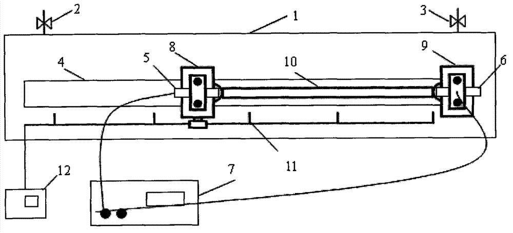
[0042] Such as image 3 The shown device includes a water tank 1, which is an airtight container, preferably the airtight container is made of stainless steel or anti-corrosion, moisture-proof materials, has a predetermined storage space inside, and has a switch with a switch on the water tank 1. The water injection port 2 and the drain port 3 with switch function, the water tank 1 injects liquid through the water injection port 2, when the liquid fills the water tank 1, it will automatically overflow from the position of the drain port 3, the injected liquid can be water or other Liquids that need to be transported through flow pipes in actual industrial production. The liquid is any suitable liquid whose velocity can be measured by an ultrasonic flowmeter.

[0043] Such as image 3 As shown, the water tank 1 is an insulated water tank. It would be better if the temperature can be controlled, which can avoid excessive temperature changes during measurement and affect the ac...

Embodiment 2

[0048] As another embodiment of the present invention, its structure is the same as that in Embodiment 1, so it will not be repeated here. In Embodiment 2, there may be a plurality of slide rail systems arranged in parallel in the water tank. A pair of probe clamping mechanisms and ultrasonic flowmeter probes are set up on the system. Multiple slide rail systems can simultaneously measure multiple pairs of ultrasonic flowmeter probe pairs. When measuring, the ultrasonic probe is positioned first, and a quartz tube with a length of about 10mm is used. The rod clamp is installed between the fixed probe clamping mechanism and the sliding probe clamping mechanism, and the clamping mechanism is tightened and the sliding probe clamping mechanism is fixed on the slide rail; the two probes of the measured flowmeter are placed in the clamping mechanism of the probe clamping mechanism In the plate, attach the end faces of the two probes to the two ends of another quartz rod with a length...


PUM


Abstract

The invention discloses a delay detection calibrating device for an ultrasonic flowmeter, which comprises a water tank, at least one slide rail system, a first ultrasonic probe and a second ultrasonic probe, wherein the water tank has an accommodating space; the slide rail system is positioned in the accommodating space of the water tank; the first ultrasonic probe and the second ultrasonic probe are a pair of ultrasonic probes of the detected flowmeter; the first ultrasonic probe is fixed on a fixed probe clamping mechanism of the slide rail system; and the second ultrasonic probe is fixed on a sliding probe clamping mechanism of the slide rail system. The delay detection calibrating device is characterized in that first data of the flowmeter is acquired at a frist distance position between the first ultrasonic probe and the second ultrasonic probe; second data of the flowmeter is acquired at a second distance position between the first ultrasonic probe and the second ultrasonic probe; and delay calibration data of the ultrasonic flowmeter is obtained by calculation of the first data and the second data. The device can be widely applicable to a universality time measurement accuracy detection device of an ultrasonic flowmeter product and has high measurement accuracy.

Description

technical field [0001] The invention relates to a detection device, in particular to a device for detecting and calibrating a probe sound wedge of an ultrasonic flowmeter and a time delay of a timing system. Background technique [0002] Ultrasonic flowmeters are widely used in the field of flow measurement, especially in large-diameter pipeline water flow (such as hydropower stations), square culvert flow and open channel flow measurement, and have become the main measurement method. The accuracy of the flowmeter is often the technical index that users are most concerned about. The detection methods for the measurement performance of ultrasonic flowmeters usually include two categories: real flow calibration and non-real flow calibration. [0003] Real-flow calibration is a relatively common detection method at present. It uses a flow standard device to generate and obtain a standard flow signal, and detects it by comparing it with the indicated value of the measured flowm...

Claims


Application Information

Patent Timeline
Patent Type & Authority Applications(China)
IPC IPC(8): G01F25/00G01F1/66
Inventor 张亮孟涛王池胡鹤鸣
Owner NAT INST OF METROLOGY CHINA
Why Eureka
Try Eureka