Underwater sound source direction estimating method

A sound source orientation and sound source technology, applied in sensor array signal processing, passive detection of underwater targets, to achieve fast detection, small size, flexible structure design

Active Publication Date: 2013-01-16
ZHEJIANG UNIV
View PDF2 Cites 34 Cited by
  • Summary
  • Abstract
  • Description
  • Claims
  • Application Information

AI Technical Summary

Problems solved by technology

In addition, the underwater sound source signal is often regarded as a broadband signal. The circular array has the characteristics that the far-field mode is independent of frequency, but at the same time, the circular array has a higher side lobe level than the main lobe.

Method used


Image

  • Underwater sound source direction estimating method
  • Underwater sound source direction estimating method
  • Underwater sound source direction estimating method

Examples


Embodiment Construction

[0029] The present invention is further illustrated below with specific examples.

[0030] The fiber optic hydrophone used in the present invention is an acousto-optic coupling interference type fiber optic hydrophone, hereinafter referred to as "fiber optic hydrophone".

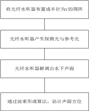
[0031] Such as figure 1 As shown, the underwater sound source orientation estimation method based on the acousto-optic coupling interference fiber optic hydrophone array of the present invention includes the following steps:

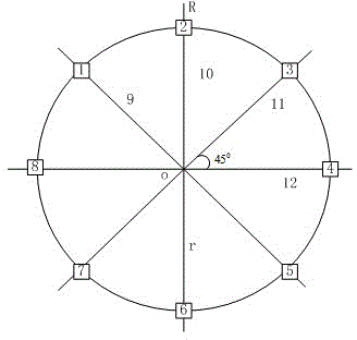
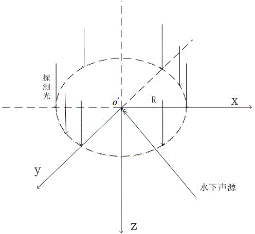
[0032] (1) Place the fiber optic hydrophone on the sliding track, which is installed on the airborne platform on the water, and the airborne platform is a certain distance from the water surface (the airborne platform can be a ship, an airplane, etc.). Adjust the position of the fiber optic hydrophone on the sliding track, so that all the fiber optic hydrophones form a uniform circular array with a radius of r. Among them, the condition that the array radius r should satisfy is: N≥4π...


PUM


Abstract

The invention discloses an underwater sound source direction estimating method, comprising the following steps of: mounting acoustic-optical coupling interference type fiber optic hydrophones on an overwater onboard platform, wherein all the acoustic-optical coupling interference type fiber optic hydrophones are arranged into a uniform round array; respectively vertically emitting probing light to a water surface by using each acoustic-optical coupling interference type fiber optic hydrophone, and generating reference light simultaneously; respectively returning each path of the probing light to the original acoustic-optical coupling interference type fiber optic hydrophone after each path of the probing light is reflected by the water surface, and carrying out related demodulation on the returned probing light through the acoustic-optical coupling interference type fiber optic hydrophones, so as to obtain underwater sound source data; and using a beam forming algorithm to process the underwater sound source data demodulated by each acoustic-optical coupling interference type fiber optic hydrophone, so as to estimate and obtain a direction of the underwater sound source. With the adoption of the underwater sound source direction estimating method provided by the invention, the rapid probing of a large-range sea area can be realized, and the full-direction estimation of a direction angle and a pitch angle of the underwater sound source can be realized. The position of the fiber optic hydrophones on a sliding rail can be adjusted, so that a uniform round array can be applicable to positioning the underwater sound source with a wider frequency band range.

Description

technical field [0001] The invention relates to an acousto-optic coupling interference fiber optic hydrophone and an underwater sound source orientation estimation method, belonging to the fields of sensor array signal processing and underwater target passive detection. Background technique [0002] Direction of Arrival (DOA) estimation has a wide range of applications in various military and national economic applications such as radar, sonar, communication, seismic exploration, radio astronomy, navigation, and sound source tracking, and has aroused great research interest. The hydrophone is an instrument for monitoring the sound field signal in water. It converts the underwater acoustic signal into an electrical signal, and then demodulates the underwater acoustic signal through the signal processing system. For the estimation of the azimuth of the underwater sound source, a physical hydrophone array is usually arranged underwater to receive the signal from the underwater ...

Claims


Application Information

Patent Timeline
Patent Type & Authority Applications(China)
IPC IPC(8): G01S5/18
Inventor 彭小东金晓峰李建龙徐文
Owner ZHEJIANG UNIV
Why Eureka
Try Eureka