Borehole-based and ground combined seismic wave space exploration method

A space detection and seismic wave technology, applied in seismology, geophysical measurement, measuring devices, etc., can solve the problems of inaccurate stratum division, inability to meet the needs of complex terrain detection, single geophone arrangement and receiving method

Active Publication Date: 2013-01-16
BEIJING MUNICIPAL ENG RES INST
View PDF5 Cites 25 Cited by
  • Summary
  • Abstract
  • Description
  • Claims
  • Application Information

AI Technical Summary

Problems solved by technology

[0004] The purpose of the present invention is to provide a seismic wave space detection method based on the combination of borehole and ground, which solves the technical problem of single geophone arrangement and receiving mode in the mid-span hole method or single hole method of the existing seismic CT technology, It cannot meet the detection needs of complex terrain, and the technical problems of stratigraphic division are not accurate enough

Method used


Image

  • Borehole-based and ground combined seismic wave space exploration method
  • Borehole-based and ground combined seismic wave space exploration method
  • Borehole-based and ground combined seismic wave space exploration method

Examples


Embodiment 1

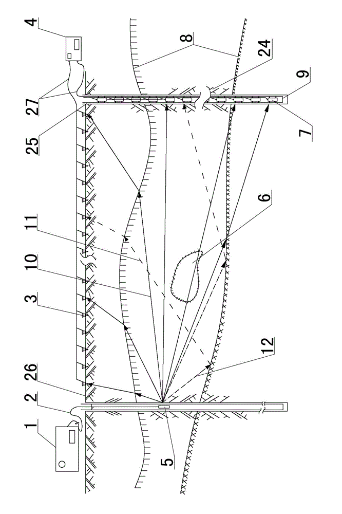
[0031] Embodiment one sees figure 1 As shown, a seismic wave spatial detection method based on the combination of borehole and ground, the steps are as follows:

[0032] Step 1. According to the topographical conditions of the site to be measured and the surrounding environment, set the excitation mode of the seismic source as excitation by the spark source generator 1, and design the arrangement mode of the geophones.

[0033] Step 2, utilize reconnaissance drill to form detection hole 25, install wall pipe 9 in the detection hole 25, the diameter of detection hole 25 can be 90mm, the outer diameter of wall pipe 9 is 90mm, and inner diameter is 80mm; Electric spark seismic source generator 1 is arranged on The surface of the ground where the source is excited, and the hole is drilled. The electric spark source generator 1 is connected to the electric spark probe 5 through the cable 2, and the electric spark probe 5 is inserted into the hole, and water is injected into the hol...

Embodiment 2

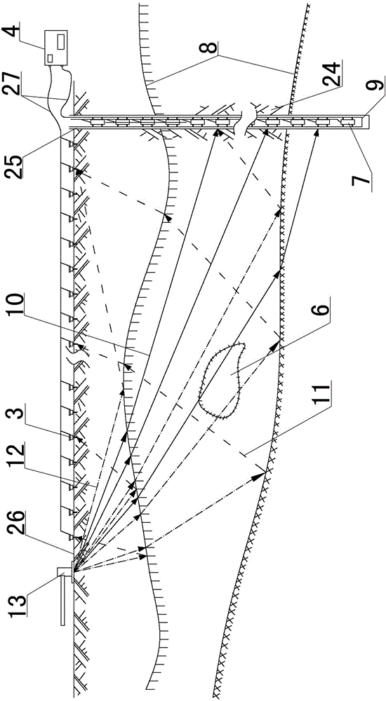
[0044] Embodiment two see figure 2 As shown, the difference from the first embodiment is that the excitation mode of setting the seismic source in the first step is artificial excitation using a hammer 13 .

[0045] The general process of data processing of seismic wave CT images is as follows:

[0046] (1) Data inspection of each channel: check the data quality, if any problem is found, it needs to be re-observed;

[0047] (2) First-arrival picking: Import the position parameter table (the position parameter table is formulated according to the relative position between the receiving point and the running point), pick up the first-arrival time of each channel, and do data processing;

[0048] (3) Calculation of the average wave velocity of rays: Preliminarily calculate the average wave velocity of each ray, find that the average wave velocity deviates from the normal range, and analyze the reason for the deviation;

[0049] (4) Forward simulation: establish the initial mod...


PUM


Abstract

The invention discloses a borehole -based and ground combined seismic wave space exploration method, which comprises the following steps of: setting an excitation mode of a seismic source and a detector arrangement mode according to a topographic condition and the peripheral environment of a field to be exploited; forming an exploration hole by using an exploration drill and mounting a wall protecting wall in the exploration hole; simultaneously arranging a detector string in a ground surface and the exploration hole; arranging a unilateral detector string in the ground surface; arranging a three-component detector string in the exploration hole; connecting both the detector strings to a data acquisition instrument on the ground; connecting the data acquisition instrument to a computer; selecting proper exploration parameters and an excitation seismic source according to the geological condition; propagating the seismic wave from the seismic source to the ground surface and the exploration hole through the stratum; performing data acquisition by using the data acquisition instrument; and finally, performing data processing and imaging through the computer. According to the method, the defect that the exploration requirement of a complex topography cannot be met due to finite span and depth for application of the conventional seismic CT (Computed Tomography) technology and single arrangement and receiving mode of the detector is overcome.

Description

technical field [0001] The invention relates to a geological survey method for a subway project, in particular to a space survey method based on an original borehole for simultaneously receiving seismic waves in the borehole and on the ground. Background technique [0002] Subway survey methods include geological survey, drilling, geophysical prospecting, in-situ testing, laboratory testing and hydrogeological testing, etc. Limited by the current level of survey technology and cost, it is impossible to achieve a fine description of various physical properties of the stratum. For example, geological surveys will face problems such as insufficient pipeline data, and it is difficult to find out abandoned underground pipelines and air-raid shelters and other structures; in subway surveys, the general spacing of drilling is 50m, and the grid is extremely sparse, which can only reveal the geological conditions of a certain point. Can the spacing meet the requirements? The continu...

Claims


Application Information

Patent Timeline
Patent Type & Authority Applications(China)
IPC IPC(8): G01V1/00
Inventor 叶英侯伟清张鹏
Owner BEIJING MUNICIPAL ENG RES INST
Why Eureka
Try Eureka