
Automatic dynamic voltage control system for wind power plant

An automatic control system and dynamic voltage technology, applied in flexible AC transmission systems, wind power generation, electrical components, etc., can solve the problems of waste of reactive power sources, decreased compensation capacity, decreased reactive power capacity, etc. Construction investment, good dynamic balance, and the effect of improving grid-connected performance

Active Publication Date: 2013-01-16
BEIJING GOLDWIND SCI & CREATION WINDPOWER EQUIP CO LTD
View PDF3 Cites 37 Cited by
  • Summary
  • Abstract
  • Description
  • Claims
  • Application Information

AI Technical Summary

Problems solved by technology

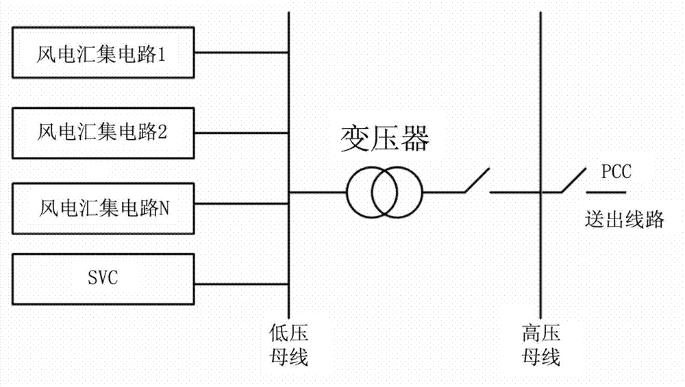
[0009] However, the AVC system of the wind farm according to the prior art has the following disadvantages: (1) To realize the voltage stability of the whole wind farm, it is necessary to install centralized reactive power compensation equipment (such as SVC or SVG), while SVC is expensive and has inherent losses, but its stability is not high; (2) When the bus voltage decreases, the ability of SVC to emit reactive power decreases, and its compensation ability decreases quadratically; (3) Prioritize the use of Centralized reactive power compensation equipment is not conducive to releasing the ability of wind turbines to generate reactive power, which causes waste of important reactive power sources; (4) The coordination between centralized reactive power compensation equipment and wind turbine operation is poor, and its characteristic is that it often lags behind real-time reactive power. power regulation demand

Method used


Image

  • Automatic dynamic voltage control system for wind power plant
  • Automatic dynamic voltage control system for wind power plant
  • Automatic dynamic voltage control system for wind power plant

Examples


Embodiment Construction

[0046] Embodiments of the invention will now be described in detail, examples of which are illustrated in the accompanying drawings, wherein like reference numerals refer to like parts throughout. The embodiments are described below in order to explain the present invention by referring to the figures.

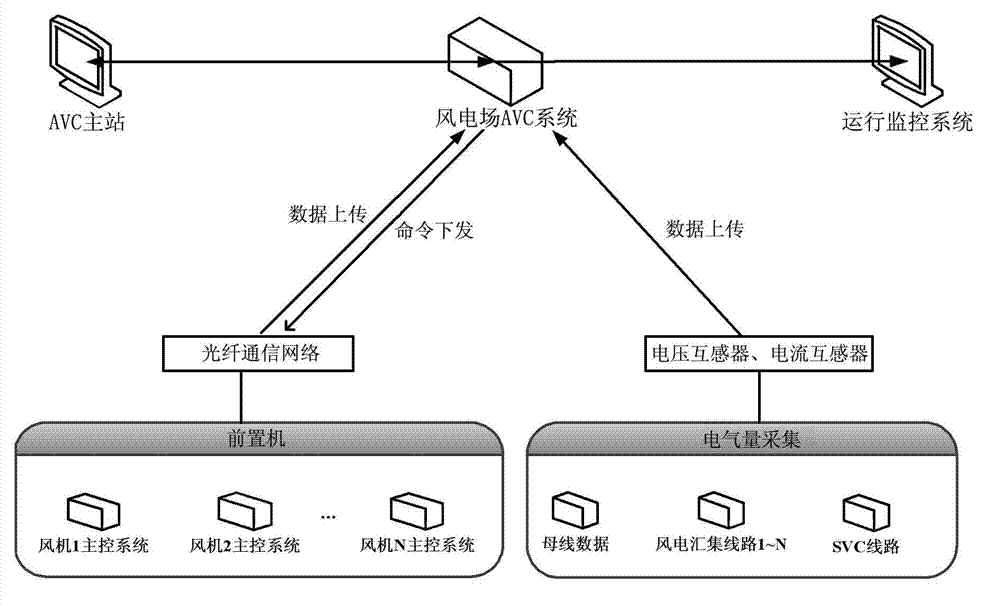
[0047] figure 2 is a diagram illustrating a wind farm AVC system according to an embodiment of the present invention.

[0048] Such as figure 2 As shown, the AVC system of a wind farm according to an embodiment of the present invention may include an AVC controller, a plurality of wind turbine main control systems arranged on a plurality of wind turbines, a centralized reactive power compensation device (for example, SVC) and a wind power transmission line, A plurality of voltage transformers and current transformers on the wind power collection line, SVC line, high-voltage busbar, and low-voltage busbar, the AVC controller communicates with the main control system of each...


PUM


Abstract

The invention provides an automatic dynamic voltage control (AVC) system for a wind power plant. The AVC system comprises an AVC controller, a plurality of blower main-control systems on a plurality of blowers in the wind power plant and an SVC (Static Var Compensator), as well as a plurality of voltage transformers and current transformers, which are arranged on wind power send-out lines, wind power collection lines, SVC lines, high-voltage buses and low-voltage buses, wherein each wind-power collection line is connected with a plurality of blowers, receives the electric energy output of the plurality of blowers and is connected with the low-voltage buses; the AVC controller communicates with each blower main-control system through an optical network and is electrically connected with the voltage transformers and the current transformers; and the AVC controller determines the total value of reactive power required to be sent out or absorbed by the wind power plant, the total value of the reactive power capable of being sent out or absorbed by all the wind power collection lines, and the reactive power capable of being sent out or absorbed by all the blowers, and sends control signals corresponding to the reactive power required to be sent out or absorbed by all the blowers to the corresponding blower main-control systems.

Description

technical field [0001] The invention relates to a dynamic automatic voltage control (AVC) system of a wind farm, and more specifically, relates to an AVC system of a wind farm capable of dynamically compensating reactive power. Background technique [0002] With the development of technology, the attention and utilization of renewable energy are increasing day by day. Among them, wind power generation is a relatively mature energy technology. However, my country's wind power industry's development plan of "building large bases and integrating into large power grids" is different from Europe's "distributed grid connection and local consumption", and has the characteristics of "large-scale" and "high concentration". Intermittent wind power causes grid voltage fluctuations, increases in system short-circuit capacity, and changes in transient stability, especially when large-scale wind power is centrally connected to the grid. At the same time, the power quality at the end of t...

Claims


Application Information

Patent Timeline
IPC IPC(8): H02J3/38H02J3/18
CPCY02E10/763H02J3/50H02J3/38H02J3/386H02J3/18Y02E40/12H02J2300/28H02J3/381H02J3/46Y02E10/76
Inventor 舒鹏乔元张毅
Owner BEIJING GOLDWIND SCI & CREATION WINDPOWER EQUIP CO LTD
Learn More