
Rolling bearing device having a hydraulic damping device

A technology for rolling bearings and equipment, which is applied to rolling contact bearings, bearings for rotational motion, bearings, etc., and can solve problems such as response performance limitations

Inactive Publication Date: 2015-05-20
SCHAEFFLER TECH AG & CO KG
View PDF5 Cites 0 Cited by
  • Summary
  • Abstract
  • Description
  • Claims
  • Application Information

AI Technical Summary

Problems solved by technology

Such plain bearings are limited by the responsiveness of the turbocharger due to friction

Method used


Image

  • Rolling bearing device having a hydraulic damping device
  • Rolling bearing device having a hydraulic damping device
  • Rolling bearing device having a hydraulic damping device

Examples


Embodiment Construction

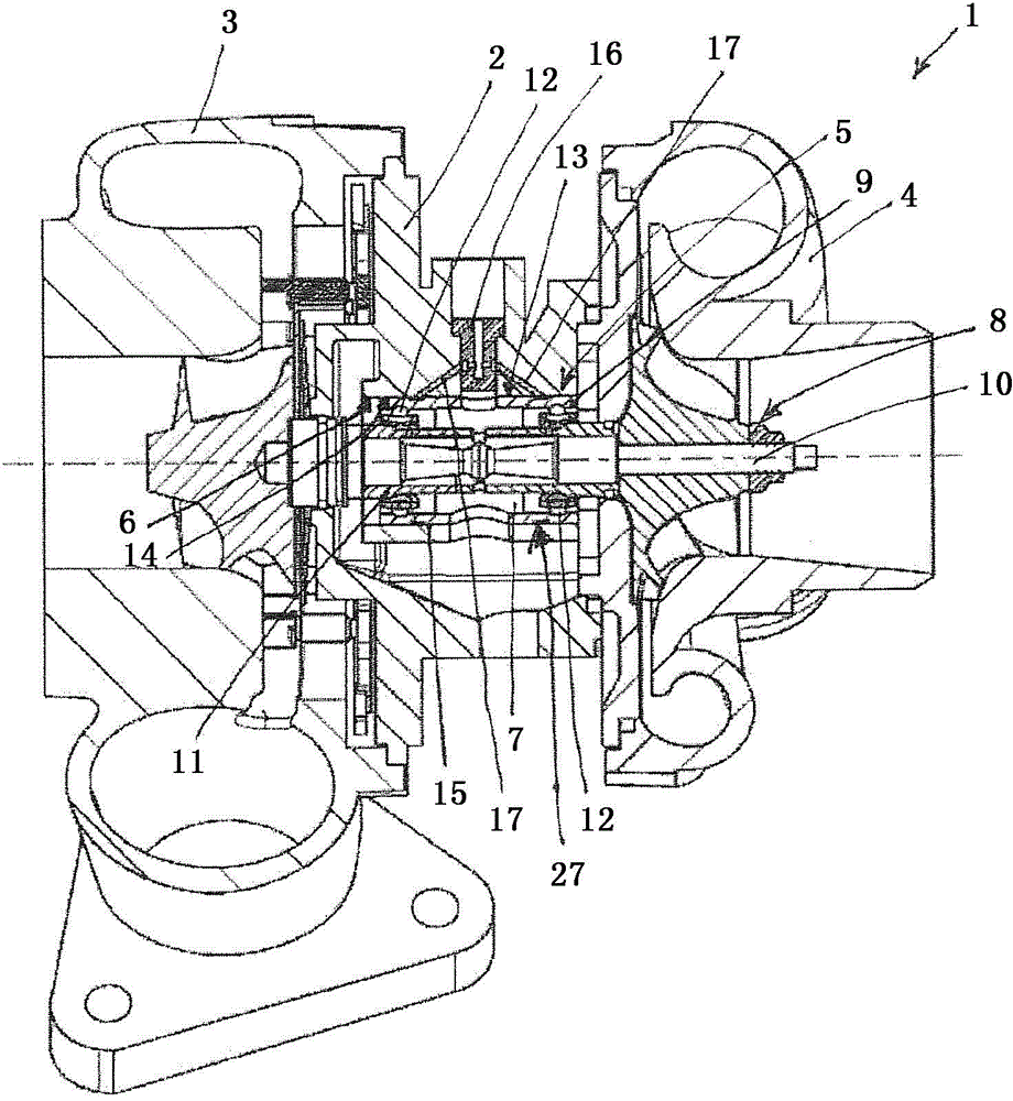
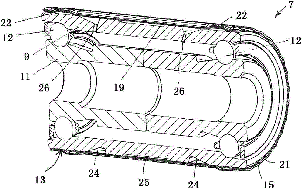
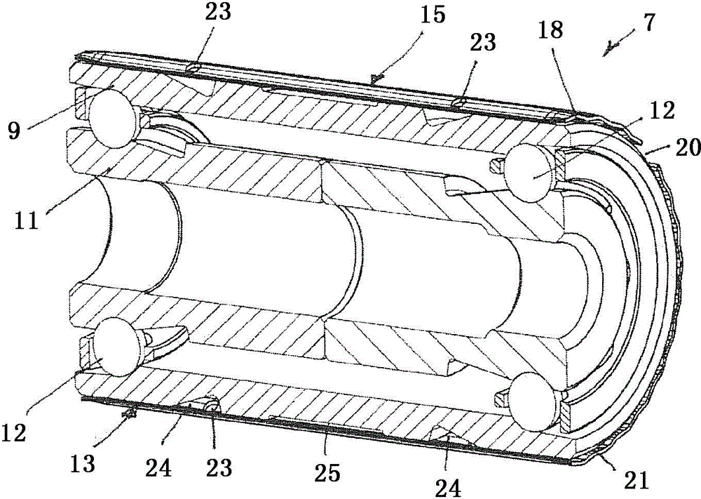
[0018] figure 1 A turbocharger 1 is shown with a housing component 2 , a compressor housing 3 and a turbine housing 4 , the housing component 2 acting as a bearing housing. The housing component 2 comprises a rolling bearing arrangement 5 with a rolling bearing 7 for rotationally mounting a rotor assembly 8 , which is accommodated radially elastically in a bearing bore 6 . To this end, the inner ring 11 of the rolling bearing 7 that can be twisted on the outer ring 9 by means of two rows of rolling elements 12 accommodates the rotor 10 of the rotor assembly, and the outer ring 9 is arranged on the outer periphery 13 of the outer ring 9 with the bearing hole The bushing 15 between the inner periphery 14 of the housing member 2 is accommodated radially elastically.

[0019] The rolling bearing arrangement 5 is supplied with hydraulic fluid via the throttle valve 16 and the fluid bore 17 , which is pressurized via folds of the bushing 15 which are not visible in this illustratio...


PUM


Abstract

A roller bearing device in particular in a turbocharger having a housing component having a bearing hole having an inner circumference and a rolling bearing received therein on an outer race having an outer circumference. In order to implement a component such as a rotor assembly of a turbocharger that can rotate on the inner circumference with great smoothness and that is protected against imbalance, a hydraulic damping device made of reservoirs filled with a hydraulic fluid and alternating along the circumference facing the outer periphery and the inner periphery is provided in an annular gap between the outer periphery of the outer race and the inner periphery of the bearing hole by radially pretensioning the outer race relative to the bearing hole.

Description

technical field [0001] The invention relates to a rolling bearing arrangement, in particular in a turbocharger having a housing component with a bearing bore with an inner circumference and in which an outer bearing with an outer circumference is accommodated radially elastically. Rolling bearings on rings. Background technique [0002] Turbochargers are known as exhaust gas turbochargers for increasing the power of internal combustion engines by increasing the flow rate of the fuel mixture into the combustion chamber of the internal combustion engine. In this case, for example, a turbine is driven by the exhaust gas of the internal combustion engine, said turbine being connected in a rotationally locked manner to a compressor which increases the gas pressure of the fuel mixture in the intake section of the internal combustion engine. The rotor assembly of the turbocharger (essentially the compressor, the turbine and the rotor shaft) is often slidably supported in bearing b...

Claims


Application Information

Patent Timeline
Patent Type & Authority Patents(China)
IPC IPC(8): F16C27/04F16C19/18
CPCF01D25/164F05D2220/40F05D2240/54F05D2300/601F16C19/184F16C27/045F16C2360/24F16F15/0237
Inventor 爱德华·戈洛瓦泰-施米特库尔特·基尔斯滕
Owner SCHAEFFLER TECH AG & CO KG
Learn More