Cutter holder and main shaft device

A technology of spindle device and tool holder, which is applied in the direction of positioning device, drive device, clamping, etc., can solve the problems of tool installation angle deviation and eccentricity, tool holder installation angle deviation and eccentricity, and difficult tool holder installation and removal, etc., to ensure easy The effect of loading and unloading and not easy to deviate

Inactive Publication Date: 2013-01-23
欧立机电株式会社
View PDF5 Cites 5 Cited by
  • Summary
  • Abstract
  • Description
  • Claims
  • Application Information

AI Technical Summary

Problems solved by technology

[0005] First of all, if it is a structure that fixes the toolholder on the rotating shaft by pressing or shrink fitting, the attachment and detachment of the toolholder is difficult, and it is not easy to replace the toolholder when, for example, the toolholder needs to be replaced. coping problems
[0006] In addition, if it is a structure in which the tool holder is fixed on the rotating shaft by screwing in, the attachment and detachment of the tool holder is relatively easy. However, due to the machining error (angular deviation, radius, etc.) The position deviation of the method), it is easy to cause the installation angle deviation and eccentricity of the toolholder, and then cause the installation angle deviation and eccentricity of the tool and other problems

Method used


Image

  • Cutter holder and main shaft device
  • Cutter holder and main shaft device
  • Cutter holder and main shaft device

Examples


Embodiment Construction

[0035] Next, Embodiment 1 of the present invention will be described according to the accompanying drawings.

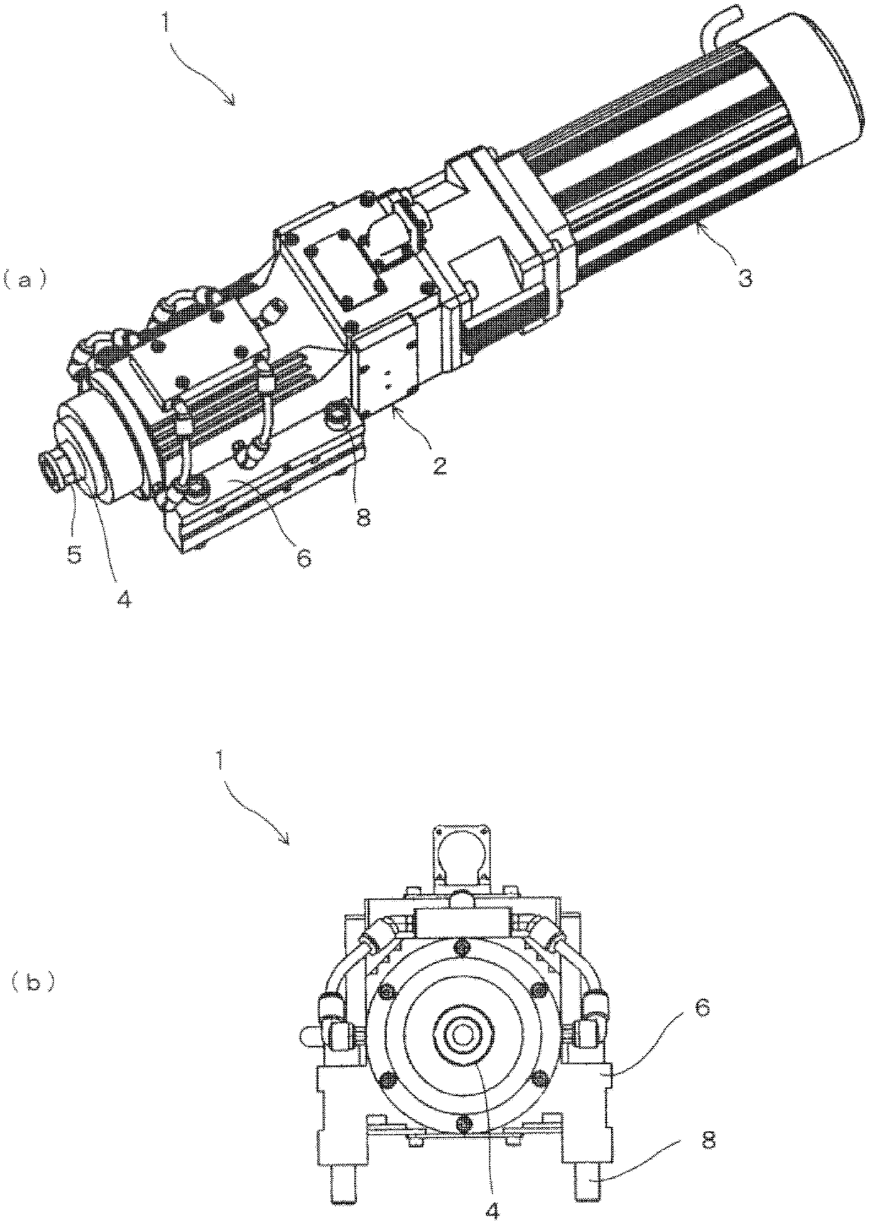
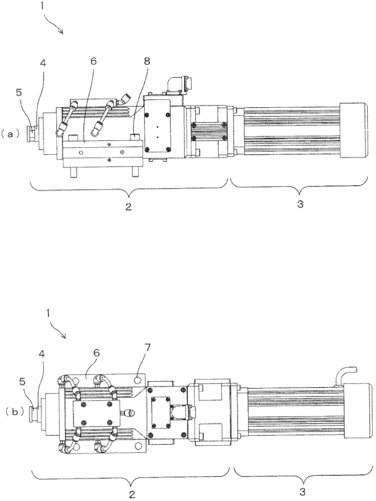
[0036] This embodiment is an example of applying the present invention to an ultrasonic spindle device. The ultrasonic spindle device 1 of the present embodiment is as Figure 1 ~ Figure 2 , is composed of ultrasonic main shaft body 2 and motor 3 . The ultrasonic spindle main body 2 has a rotating shaft 4 (spindle) driven and rotated by a motor 3, and a bearing mechanism for holding the rotating shaft 4 rotatably and vibratingly. Ultrasonic vibration excitation unit (for example, composed of piezoelectric elements), cooling mechanism, etc. In addition, the ultrasonic vibration applied to the rotating shaft 4 is a vibration having a frequency equivalent to that of the ultrasonic wave, usually an axial vibration, and its amplitude is, for example, only several μm.

[0037] Such as figure 1 As shown in (a) etc., the distal end portion of the rotating shaft 4 is expos...


PUM


Abstract

The invention provides a cutter holder and a main shaft device, wherein the cutter holder (20) is mounted on a rotating shaft (4) of the main shaft device and holds the cutter (50), ensuring mounting and dismounting relative to the rotating shaft (4) and at least uneasily-generated deviation of the mounting angle relative to the rotating shaft (4). The constitution is that: a cutter fixing part (21) which fixes the cutter (50) is arranged on a top end side, a base end face (22) (a joint face at the cutter holder side) which joints with a top end face (10) of the rotating shaft (4) (a joint face at the rotating shaft side) is formed on a base end side, and in addition, a mounting shaft (23) which protrudes form a center of the base end face (22) towards an axial direction is also formed on the base end side, the periphery of the mounting shaft (23) is provided with a screw thread part (23) which is in screw joint with a screw thread hole (11) that is formed at a center of a top end of the rotating shaft (4), and the mounting shaft (23) is of an elastically deformable structure (a structure having gaps (29)).

Description

technical field [0001] The invention relates to a tool holder and a spindle device using the tool holder. Background technique [0002] In general, a spindle device used in drilling, milling, etc. is disclosed in, for example, Patent Document 1, which has a rotating shaft (spindle) on which a cutting tool (tool) is attached at the tip. In this spindle device, a tool holder (sometimes referred to as a jig or the like) for holding a tool with respect to a rotary shaft has conventionally been attached and fixed to the rotary shaft by press fitting, screwing in, or shrink fitting. For example, in Patent Document 1 figure 1 and figure 2 discloses a structure in which the tool holder 3 (shrink fitting holder 30 ) is fixed to the fixing hole 2 a of the rotary spindle 2 by press fitting. [0003] Patent Document 1: Japanese Patent Laid-Open No. 2010-207972 [0004] However, in the above-mentioned conventional spindle device, there are problems as follows with regard to the moun...

Claims


Application Information

Patent Timeline
Patent Type & Authority Applications(China)
IPC IPC(8): B23B19/02B23Q3/12
CPCB23B31/11B23B31/34B23C5/26B23C2270/10B23Q3/12B23Q5/043
Inventor 田中实荒井俊
Owner 欧立机电株式会社
Why Eureka
Try Eureka