V-type belt wheel

A technology of pulleys and pulleys, applied in the direction of belts/chains/gears, components with teeth, hoisting devices, etc., which can solve the problems of low manufacturing cost of pulleys, high manufacturing costs of pulleys, and easy wear of V-belt pulleys, etc. Problems, to achieve the effect of not easy to slip, not easy to wear, not easy to break

Active Publication Date: 2013-01-23
杭州金瀚能源科技有限公司
View PDF5 Cites 9 Cited by
  • Summary
  • Abstract
  • Description
  • Claims
  • Application Information

AI Technical Summary

Problems solved by technology

[0007] The present invention overcomes the disadvantages of the existing V-belt pulleys, such as easy wear, short service life, and high manufacturing cost of the pulley, and provides a V-shaped pulley, ...

Method used


Image

  • V-type belt wheel
  • V-type belt wheel
  • V-type belt wheel

Examples


Embodiment 1

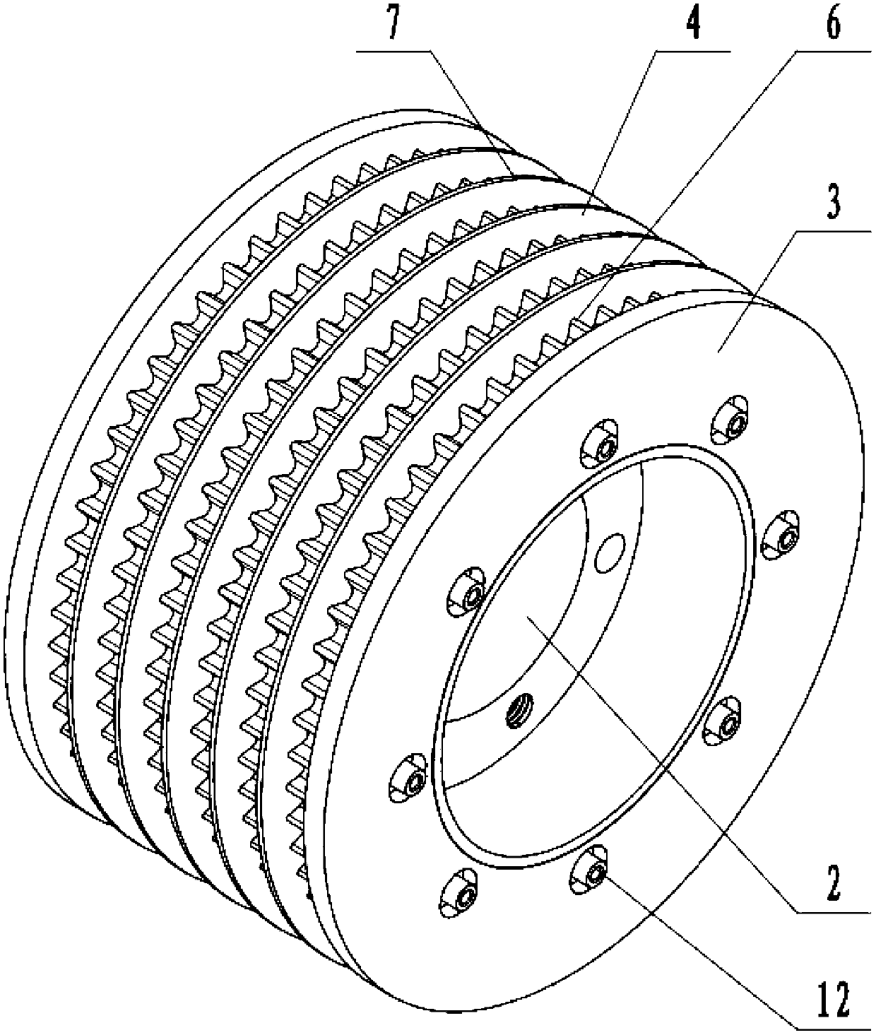
[0036] Embodiment 1: a kind of V-type belt pulley (referring to attached figure 1 , attached figure 2 ), including a cylindrical pulley body 1, a through hole 2 is provided in the center of the pulley body, and a positioning ring 29 is provided at both ends of the pulley body (see attached Figure 5 ), the positioning ring is close to the edge of the through hole and coaxial with the through hole, the inner diameter of the positioning ring is the same as the aperture of the through hole, and the inner wall of the through hole of the main body of the pulley is provided with an inwardly protruding annular protruding ring 30, and the two ends of the protruding ring They are arranged inside the two ends of the main body of the pulley respectively, and the protruding rings are integrated with the main body of the pulley, and the end faces of the protruding rings are provided with six axial conduction holes 31 . The main body of the pulley is connected with a wheel, and the wheel ...

Embodiment 2

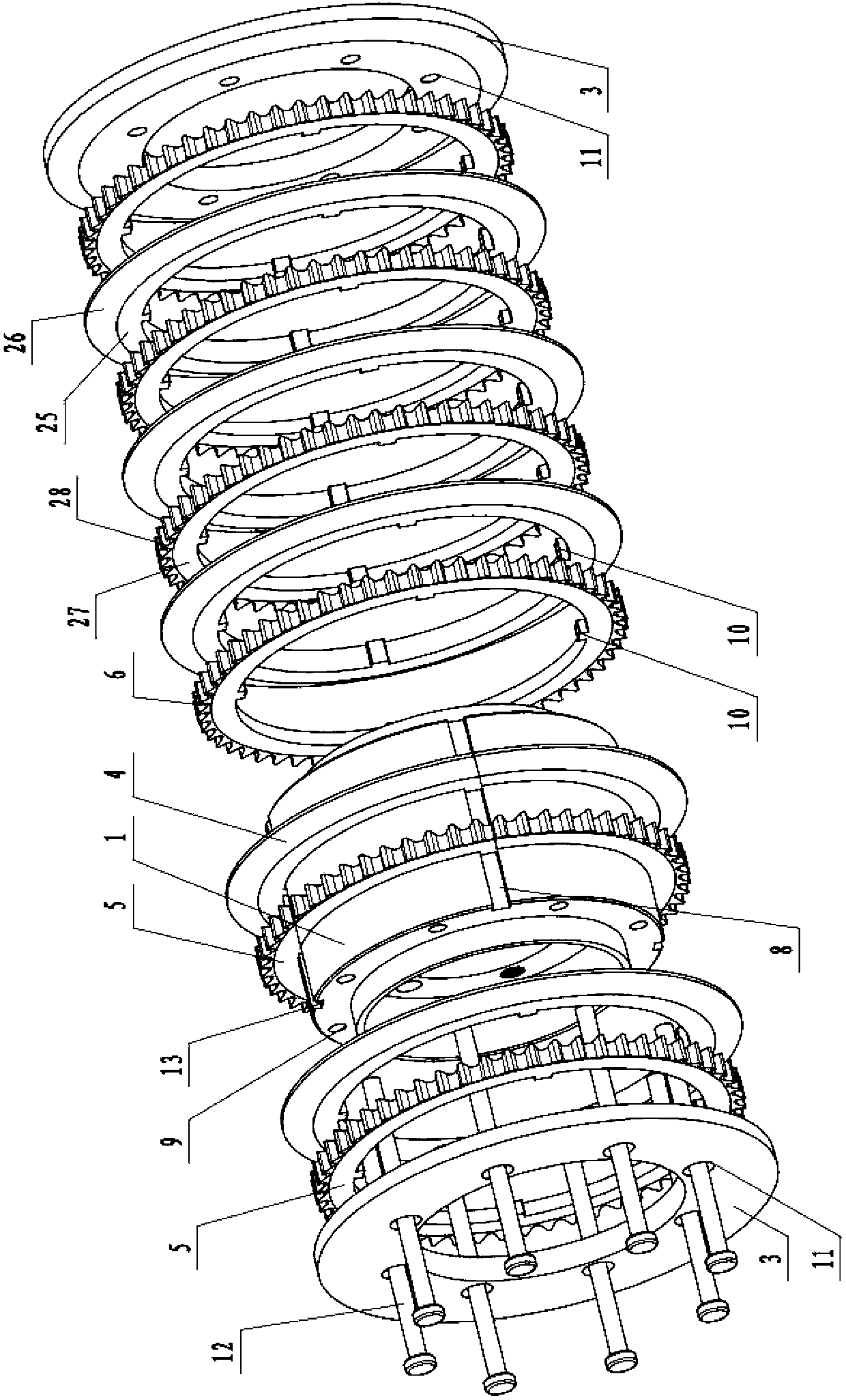
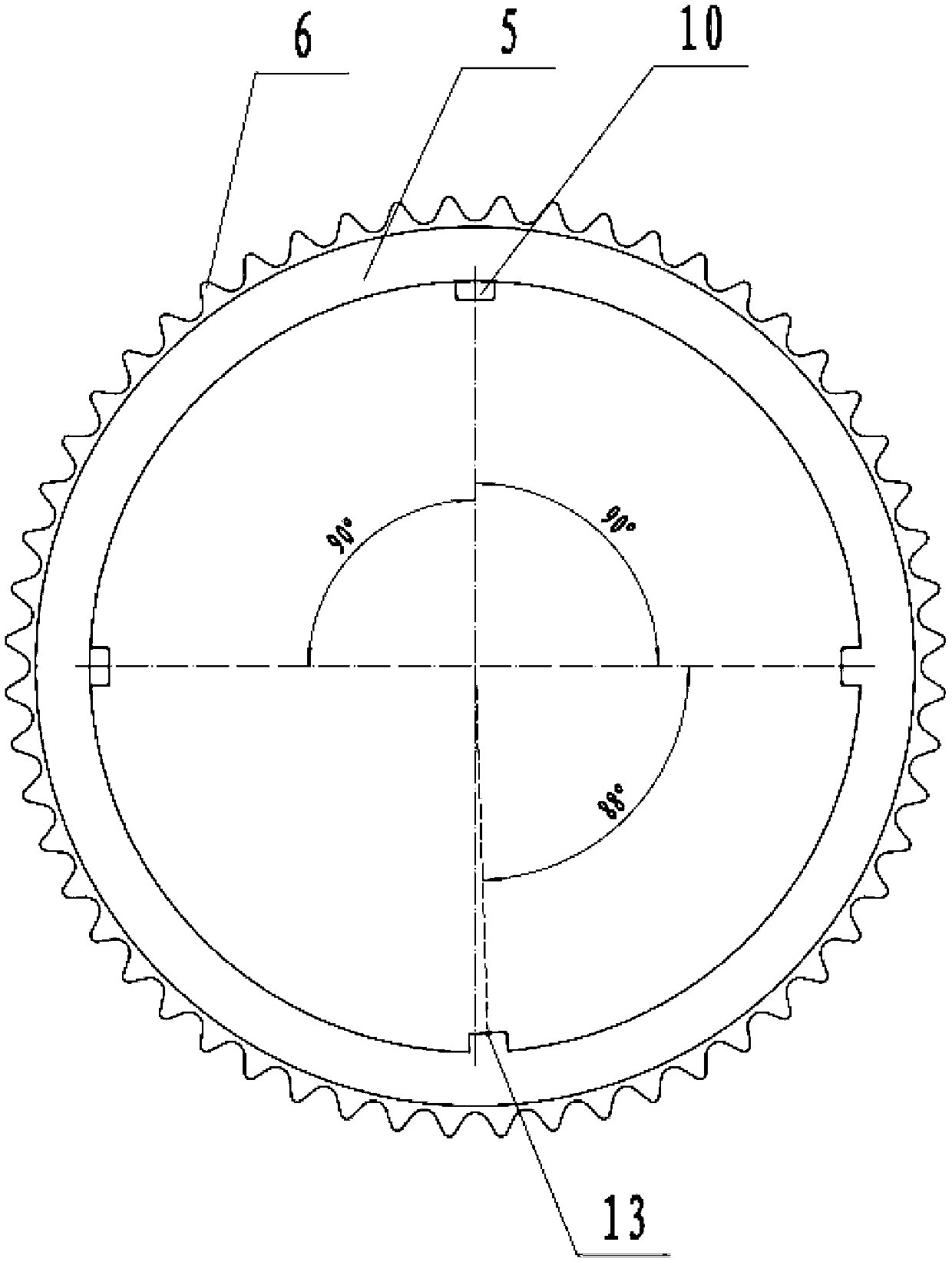
[0040] Embodiment 2: a kind of V-shaped belt pulley (referring to attached Image 6 ), consisting of a cylindrical pulley body 1 (see attached Figure 10 , attached Figure 11 ), the center of the main body of the pulley is provided with a through hole 2. The main body of the pulley includes a coaxial inner ring body 32 and an outer ring body 33. The inner ring body and the outer ring body are connected by six connecting ribs 34 evenly distributed. On the inner side of the two ends, the inner ring body, the connecting rib and the outer ring body are connected together to form an integral structure. The inner hole of the inner annular body is used as the through hole of the main body of the pulley. The main body of the pulley is connected with a wheel piece, and the wheel piece includes an outer wheel piece 3 and an inner wheel piece 4. An outer wheel piece is respectively provided at both ends of the pulley body, and one of the two outer wheel pieces is the first outer whee...


PUM


Abstract

The invention discloses a V-type belt wheel, aiming at solving the shortcomings that an existing V-type wheel is easy to abrade and short in service life and the manufacturing cost of the belt wheel is high. The V-type belt wheel comprises a belt wheel body, wherein a through hole is arranged at the center of the belt wheel body; wheel sheets are connected on the belt wheel body; the wheel sheets comprise outer wheel sheets and inner wheel sheets; the outer wheel sheet is arranged at each one of the two ends of the belt wheel body; coaxial annular tooth-shaped sheets and annular inner wheel sheets are alternatively arranged between the two outer wheel sheets; the diameters of the tooth-shaped sheets are less than the diameters of the inner wheel sheets; the outer wheel sheets, the tooth-shaped sheets and the inner wheel sheets are fixedly connected by connection structures; meshed teeth which are in convex-concave interval are arranged at the outer peripheral surfaces of the tooth-shaped sheets; adjacent two wheel sheets and tooth-shaped sheets which are placed between the two adjacent wheel sheets form a V-type belt trough; the opposite end surfaces of the two adjacent wheel sheets form the side faces of a friction transmission belt trough; the tooth-shaped sheets placed between the two adjacent wheel sheets form a meshed transmission belt tooth; and the side faces of the belt trough are inclined smooth faces.

Description

[0001] technical field [0002] The invention relates to a pulley, and more specifically relates to a V-shaped pulley with convenient installation, good strength, long service life and high transmission efficiency. [0003] Background technique [0004] In the prior art, force is generally transmitted between the V-shaped transmission belt and the pulley through sliding friction. In actual use engineering, the belt will undergo certain elongation and deformation. When the smaller driving pulley drives the larger driven pulley, the wrap angle of the large pulley is larger than that of the small pulley, so that the belt is easy to The phenomenon of slipping occurs on the small pulley, especially under the working conditions of high power and heavy load, the slipping phenomenon is more obvious. In order to overcome the slipping phenomenon, people have designed a V-belt transmission system with meshing transmission. This pulley includes a pulley body with a groove. The ...

Claims


Application Information

Patent Timeline
IPC IPC(8): F16H55/38
Inventor 汪金芳
Owner 杭州金瀚能源科技有限公司
Why Eureka
Try Eureka