Inward depressurizing high pressure soft sealing ball valve

A soft-sealing, high-pressure technology that is applied to valve details, valve devices, valve housing structures, etc., can solve the problem of large opening and closing torque of the valve seat, and achieve the effects of small friction, less wear and reliable mechanism

Inactive Publication Date: 2013-01-23
骆薛平
View PDF6 Cites 4 Cited by
  • Summary
  • Abstract
  • Description
  • Claims
  • Application Information

AI Technical Summary

Problems solved by technology

[0005] The invention provides a high-pressure soft-sealed ball valve with internal pressure relief, which solves the practical problem that when the soft-sealed floating ball valve is applied to high-pressure wo...

Method used


Image

  • Inward depressurizing high pressure soft sealing ball valve
  • Inward depressurizing high pressure soft sealing ball valve
  • Inward depressurizing high pressure soft sealing ball valve

Examples


Embodiment 2

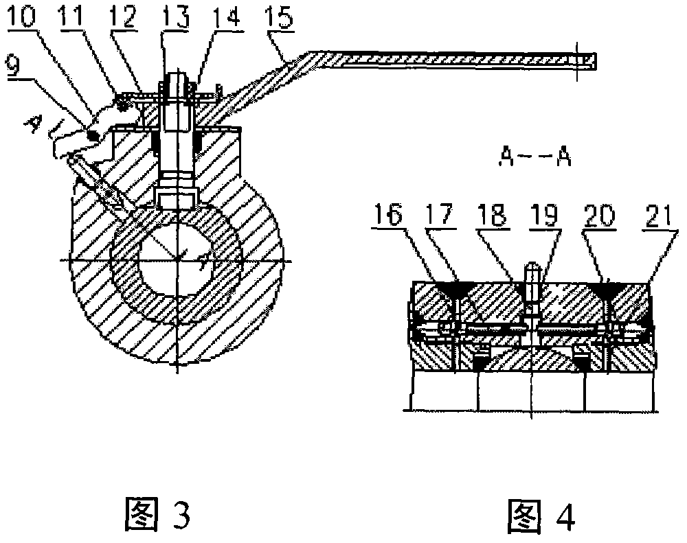
[0030] Such as figure 2 , image 3 with Figure 4 As shown, the flange in the middle hole of the valve is provided with screw holes for connecting the support plate 3 or the operator, and the support plate 3 is connected with the pendulum positioning link 10 through the positioning pin 9 . The pendulum positioning link 10 can swing along the axis of the positioning pin 9.

Embodiment 3

[0032] Such as figure 2 , image 3 with Figure 4 As shown, the valve is equipped with a locking mechanism, the connecting end of the pendulum positioning link 10 and the pressure plate handle 12 is provided with a positioning part, and the handle 15 and the outer edge of the valve stem sleeve are provided with two positioning grooves arranged at 90 degrees. The concavo-convex of the positioning part of the pendulum positioning connecting rod 10 matches, and the valve opening and pipe positions can be locked.

Embodiment 4

[0034] Such as figure 2 , image 3 with Figure 4 As shown, the two ends of the bypass are respectively provided with check valves, and the plunger 18 moves axially through the downward pressure of the pendulum positioning connecting rod 10, and the inclined wedge mechanism of the plunger 18 drives the slide rod 17 to translate, pushing away the steel ball 16, the spring 20 Open the check valve, and the internal pressure relief system is connected.


PUM


Abstract

The invention relates to a valve, and particularly relates to an inward depressurizing high pressure soft sealing ball valve. The inward depressurizing high pressure soft sealing ball valve comprises a valve body, a valve cover, a valve rod, a ball body, a valve seat, a swing positioning connecting rod, a platen handle, an operating handle, a locking mechanism C, an inclined wedging mechanism E and a decompression runner L, wherein the swing positioning connecting rod is connected with the platen handle; the swing positioning connecting rod is driven by the platen handle to carry out the swing motion; a slider is driven by the inclined wedging mechanism E of a sinker rod to push a steel ball and a spring to open a check valve; the valve body is internally provided with a pressure release system; the pressure release system pushes the slider F and the steel ball G by the inclined wedging mechanism of the external sinker rod E so that a bypass pipe L can be communicated with a bypass pipe B; and the built-in pressure release system can realize the connection of the automatic operation of manual operation, power drive, pneumatic drive or hydraulic drive through an external connecting device.

Description

technical field [0001] The invention relates to a new type of valve, in particular to a high-pressure soft-sealed ball valve with internal pressure relief. Background technique [0002] The ball of the traditional high-pressure soft-sealed ball valve is supported by the valve seats at both ends. When the valve is in a normal state, the ball groove is placed in the center of the rotating body, which coincides with the axis of the valve stem; when the valve is under pressure, due to the pressure of the pipeline and the seat Due to factors such as material elastic deformation, the axis of the ball will deviate from the axis of the valve stem, which will affect the opening and closing torque of the valve. Usually, after the pressure reaches 3000 psa or more, the valve cannot be started due to the above reasons, and the transmission of the ball and the valve stem will fall off or be damaged. Phenomenon. [0003] Ball valves are classified according to their structural principles...

Claims


Application Information

Patent Timeline
IPC IPC(8): F16K5/06F16K5/08F16K35/00F16K27/06F16K27/12
Inventor 骆薛平
Owner 骆薛平
Why Eureka
Try Eureka