Cable fixing clamp and cable fixing device employing cable fixing clamp

A fixing device and fixing clip technology, applied in the direction of electrical components, pipe supports, pipes/pipe joints/fittings, etc., can solve the problem that the installation performance affects the reliability and stability of the power supply system, cannot meet the strict process requirements of the cable head, and affects the sleeve. Insulation performance of pipes and cable heads, etc., to avoid deformation or damage and influence on insulation performance, improve clamping firmness, and uniform force

Inactive Publication Date: 2013-01-23
XUJI GRP +2
View PDF8 Cites 20 Cited by
  • Summary
  • Abstract
  • Description
  • Claims
  • Application Information

AI Technical Summary

Problems solved by technology

At present, two fixed points are generally set before the cable phase separation and at the cable head to implement cable fixing, and when fixing, the installation technicians often rely on the experience of the installation technician to obtain materials on the spot and carry out mechanical fixing, which is neither reliable nor satisfactory for the production of the cable head. Strict process requirements in the process
In addition, due to the weight of the cable and the electric force, the cable head will be stressed, or the cable length error will cause bending stress to the cable head after the cable is phase-separated, which will affect the insulation performance of the bushing and the cable head, resulting in power supply failure. The installation performance of electrical equipment directly affects the reliability and stability of the power supply system
[0003] Chinese patent document CN202302322U discloses a cable fixing clip, which includes a clip seat and a clip cover that are connected by fastening bolts to clamp the cable after movable docking. Finally, it forms a cylindrical clamping cable. This structure is only suitable for clamping cables with fixed wire diameter specifications or cables with a small diameter range. For cables with slightly larger or smaller diameters, the clamping is not tight and cannot Reliable fixing of cables

Method used


Image

  • Cable fixing clamp and cable fixing device employing cable fixing clamp
  • Cable fixing clamp and cable fixing device employing cable fixing clamp
  • Cable fixing clamp and cable fixing device employing cable fixing clamp

Examples


Embodiment Construction

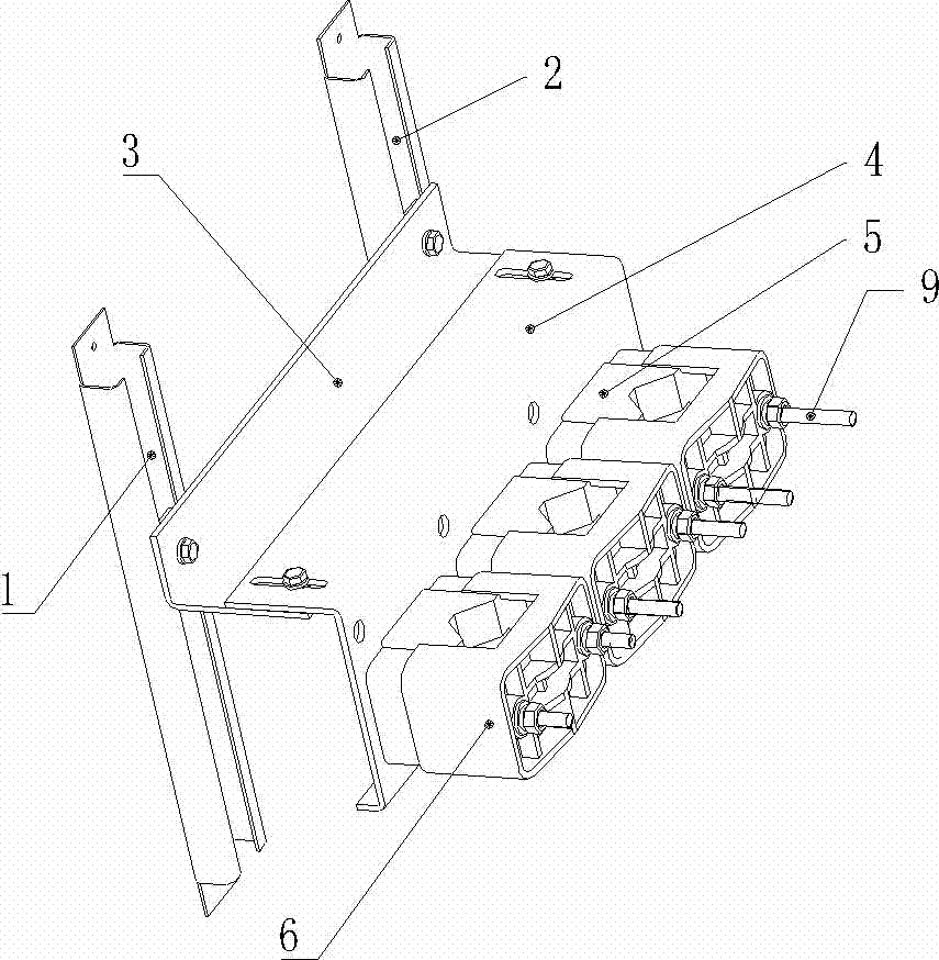
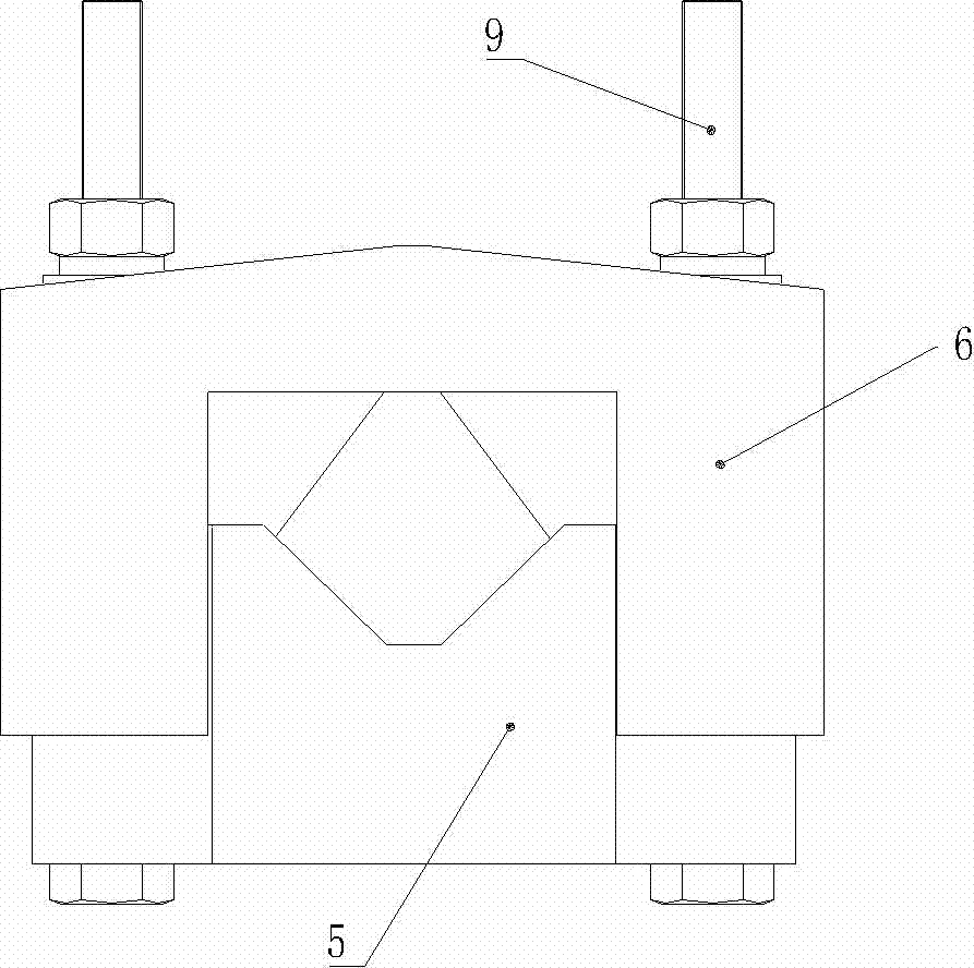
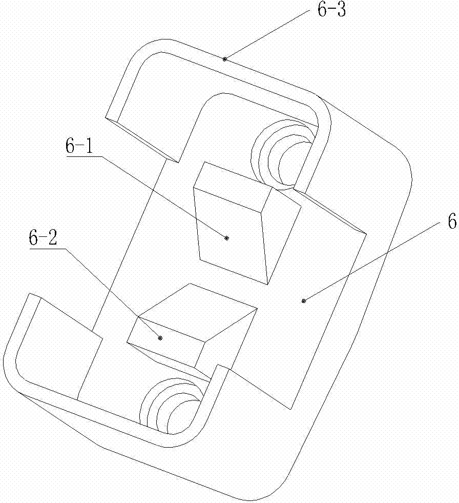
[0023] The embodiment of the cable fixing device provided by the present invention see Figure 1-Figure 5 As shown, it includes an adjustable mounting frame and three cable fixing clips fixedly installed on the adjustable mounting frame. By adjusting the adjustable mounting frame, the height, front and rear positions of the cable fixing clips can be adjusted to suit the desired Fixed position of clamped cable head.

[0024] The adjustable mounting frame includes a fixed plate 4 bent into an L shape and a connecting plate 3 bent into an L shape, and three cable fixing clips are installed in parallel on one side plate of the fixed plate 4, and the other side plate of the fixed plate Connected to one side plate of the connecting plate 3 by bolts, the board surfaces of the two side plates are stacked and fixedly connected together by bolts, wherein the threaded mounting holes provided on the fixing plate 4 are long holes, and the long holes The length direction of the cable fixin...


PUM


Abstract

The invention relates to a cable fixing device, which comprises an adjustable mounting rack capable of adjusting high, low, front and rear positions of cable fixing clamps and at least one cable fixing clamp which is fixedly arranged on the adjustable mounting rack, wherein each cable fixing clamp comprises a clamping seat used for clamping a cable through a locking device after the alignment of the cable and a clamping cover; clamping through slots for clamping the cable are formed in the clamping seats; hollow cavities are respectively formed in two side walls of the clamping through slots; clamping bulges which can be inserted into the corresponding hollow cavities when the clamping covers and the clamping seats are aligned are arranged on aligned end faces of the clamping covers; and cable clamping surfaces on the clamping bulges and the clamping through slots on the clamping seats form cable clamping space of which the size is changed along with change of the alignment depth of the clamping covers and the clamping seats. By the cable fixing device, the stress of mechanical fastening on the cable can be reduced, the cable mounting reliability is improved, faults of cable heads are reduced, and the same cable fixing clamp can be matched with cables of different wire diameters. The invention also relates to a cable fixing clamp.

Description

technical field [0001] The invention relates to a cable fixing clip and a cable fixing device which can be used in a high-voltage switch cabinet to clamp and fix cables. Background technique [0002] After the high-voltage switchgear and cables are laid, in order to make it a continuous power supply line, it is necessary to use the plug-in cable head to complete the connection and fixation of the cable and the bushing. At present, two fixed points are generally set before the cable phase separation and at the cable head to implement cable fixing, and when fixing, the installation technicians often rely on the experience of the installation technician to obtain materials on the spot and carry out mechanical fixing, which is neither reliable nor satisfactory for the production of the cable head. Strict process requirements in the process. In addition, due to the weight of the cable and the electric force, the cable head will be stressed, or the cable length error will cause b...

Claims


Application Information

Patent Timeline
Patent Type & Authority Applications(China)
IPC IPC(8): F16L3/10H02G3/04
Inventor 吴小钊曹志民郑晓果徐慧强汤清双
Owner XUJI GRP
Why Eureka
Try Eureka