Self-power supply vibration sensor based on ZnO nanowires and manufacturing method thereof

A vibration sensor, self-powered technology, applied in instruments, using electrical devices, using electromagnetic means, etc., can solve the problems of large size and weight, and achieve the effects of small size, light weight, and prolonged vibration time

Inactive Publication Date: 2013-01-23
THE NAT CENT FOR NANOSCI & TECH NCNST OF CHINA
View PDF6 Cites 9 Cited by
  • Summary
  • Abstract
  • Description
  • Claims
  • Application Information

AI Technical Summary

Problems solved by technology

[0004] The purpose of the present invention is to provide a self-powered vibration sensor based on ZnO nanowires to solve the problems of existing vibration sensors with large volume and weight and the need for external power supply

Method used


Image

  • Self-power supply vibration sensor based on ZnO nanowires and manufacturing method thereof
  • Self-power supply vibration sensor based on ZnO nanowires and manufacturing method thereof
  • Self-power supply vibration sensor based on ZnO nanowires and manufacturing method thereof

Examples


Embodiment 1

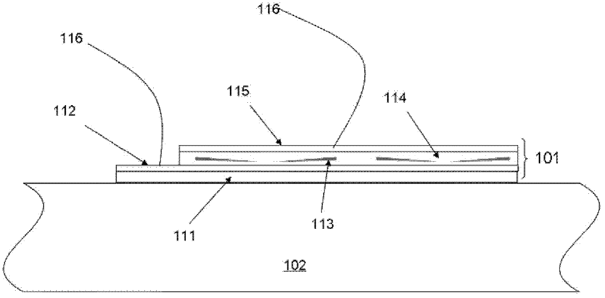
[0054] This embodiment provides a image 3 The self-powered vibration sensor shown consists of:

[0055] PI (polyimide) substrate 111 with a thickness of about 200 μm;

[0056] Cr / Au lower electrode 112 on substrate 111;

[0057] PMMA (polymethyl methacrylate) dielectric layer 114 on the lower electrode 112;

[0058] Cr / Au upper electrode 115 on PMMA dielectric layer 114;

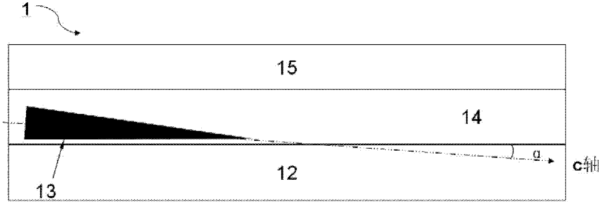
[0059] A plurality of conical ZnO nanowires 113 grown in the c-axis direction are randomly distributed in the dielectric layer, roughly parallel to the upper and lower electrodes, and insulated from the upper and lower electrodes;

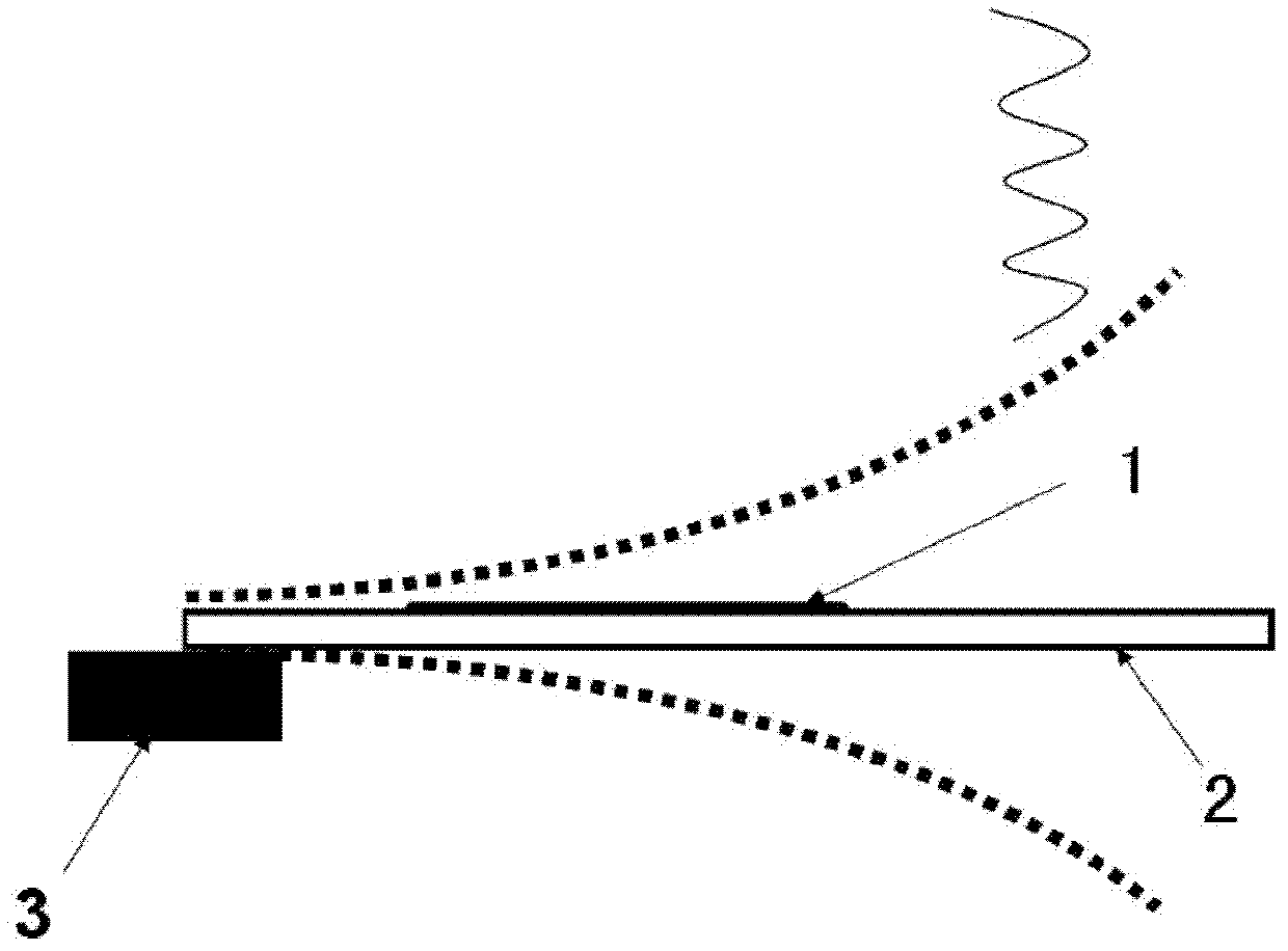
[0060] Cantilever beam 102 supports the dielectric layer and ZnO nanowires between the upper and lower electrodes and the two, and one end of cantilever beam 102 is fixed on the fixed plate (the structure of the fixed plate is the same as that of the fixed plate) figure 1 Same as in , for clarity in image 3 not shown in);

[0061] Two lead wires 116 are electrically conne...

Embodiment 2

[0074] This embodiment provides a Figure 6 The self-powered vibration sensor shown consists of:

[0075] PI (polyimide) substrate 211 with a thickness of about 200 μm;

[0076] Cr / Au lower electrode 212 on substrate 211;

[0077] The first sub-dielectric layer 214a and the second sub-dielectric layer 214b on the lower electrode 212, each sub-dielectric layer 214a, 214b has a plurality of tapered ZnO nanowires 213 grown in the c-axis direction, ZnO nanometer The line 213 is roughly parallel to the upper and lower electrodes and insulated from the upper and lower electrodes, and the first and second sub-dielectric layers are made of PMMA;

[0078] Cr / Au upper electrode 215 on the second sub-dielectric layer 214b;

[0079] Cantilever beam 202 supports the dielectric layer and ZnO nanowires between the upper and lower electrodes and the two, and one end of the cantilever beam 202 is fixed on the fixed plate (the structure of the fixed plate is the same as that of the fixed pla...

Embodiment 3

[0092] This embodiment provides a Figure 7 The self-powered vibration sensor shown consists of:

[0093] Fixed on the fixed piece (the structure of the fixed piece is the same as figure 1 Same as in , for clarity in Figure 7 Not shown in the cantilever beam 302 on), made of conductive material;

[0094] Dielectric layer 314 on cantilever beam 302;

[0095] an upper electrode 315 on the dielectric layer 314;

[0096] A plurality of tapered ZnO nanowires 313 grown in the c-axis direction are located in the dielectric layer, approximately parallel to the upper electrode and the cantilever beam 302 , and insulated from the upper electrode and the cantilever beam 302 .

[0097] The dielectric layer, the upper electrode, and a plurality of tapered ZnO nanowires together constitute the sensor element 301 .

[0098] The self-powered vibration sensor provided by this embodiment can be made by the following methods:

[0099] 1) Spin coating a dielectric material layer with a thi...


PUM


Abstract

The invention provides a self-power supply vibration sensor. The self-power supply vibration sensor comprises a cantilever beam and a self-power supply vibration sensor element on the cantilever beam, wherein the self-power supply vibration sensor element comprises an upper electrode and a lower electrode, a dielectric layer arranged between the upper electrode and the lower electrode, and a plurality of nanostructures with a piezoelectric effect, which are positioned in the dielectric layer, wherein the nanostructures are insulated from the upper electrode and the lower electrode and are almost parallel to the upper electrode or the lower electrode. The invention further provides a self-power supply vibration sensor device and a manufacturing method of the self-power supply vibration sensor.

Description

technical field [0001] The invention relates to a self-powered vibration sensor and a manufacturing method thereof, in particular to a self-powered vibration sensor made of conical ZnO nanowires and a manufacturing method thereof. Background technique [0002] In the prior art, there are many types of vibration sensors, and the core parts of these devices are mostly piezoelectric ceramic sheets or thin films based on PZT, and Pb (lead) contained in PZT seriously pollutes the environment. Moreover, vibration sensors in the prior art generally have complex structures, high manufacturing precision requirements, relatively large volume and weight, and require an external power supply. These shortcomings limit the wide application of vibration sensors. [0003] ZnO nanowire has excellent environmental friendliness and is a green piezoelectric material. In 2007, Professor Wang Zhonglin of Georgia Institute of Technology in the United States observed the power generation of ZnO fo...

Claims


Application Information

Patent Timeline
Patent Type & Authority Applications(China)
IPC IPC(8): G01H11/06
Inventor 王中林于爱芳江鹏
Owner THE NAT CENT FOR NANOSCI & TECH NCNST OF CHINA
Why Eureka
Try Eureka