
Method for estimating target distance based on dual-waveband infrared radiation

A technology of target distance and infrared radiation, applied in the field of infrared detection, can solve the problems of unsuitable early warning or other frontal attack weapon systems, non-unique distance, difficult target distance estimation, etc., achieve good target distance estimation effect, increase Space overhead, the effect of enhancing penetration capabilities

Inactive Publication Date: 2013-01-23
XIDIAN UNIV
View PDF2 Cites 6 Cited by
  • Summary
  • Abstract
  • Description
  • Claims
  • Application Information

AI Technical Summary

Problems solved by technology

The early ranging range was 2.8km, and later developed to 11km; however, the above-mentioned measurement methods require observation of the target behind or behind the side, and are not suitable for early warning or other frontal engagement weapon systems
Later, the document "Wallace Joseph. Passive range determination of object [P]. Inter. Patent, WO055643, 2000." proposed a method of using dual-band infrared radiation information to determine the target distance, but the working curve of this method has serious non-linearity. Linear, the calculated distance is not unique, and the resulting distance estimate is unreliable and difficult to use for actual target distance estimation

Method used


Image

  • Method for estimating target distance based on dual-waveband infrared radiation
  • Method for estimating target distance based on dual-waveband infrared radiation
  • Method for estimating target distance based on dual-waveband infrared radiation

Examples


Embodiment Construction

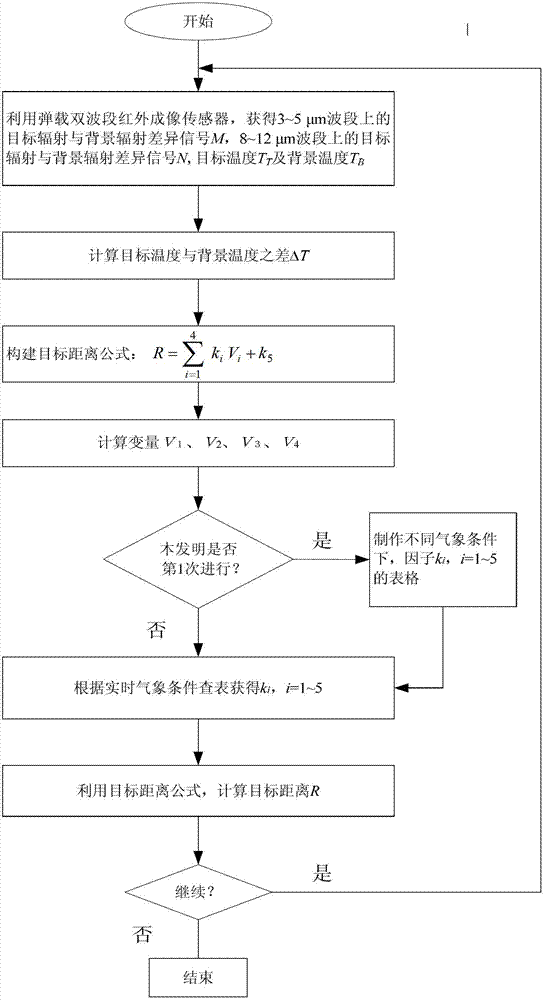
[0025] refer to figure 1 , the implementation steps of the present invention are as follows:

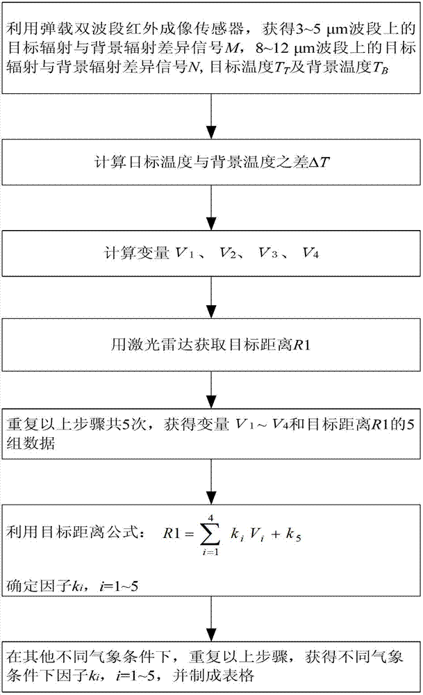
[0026] Step 1, use the missile-borne dual-band infrared imaging sensor to obtain the relevant parameters of the target and the background.

[0027] 1.1) Use the missile-borne dual-band infrared imaging sensor to obtain infrared image grayscale information, and use the linear relationship between radiance and pixel grayscale to obtain the difference signal M between target radiation and background radiation in the 3-5 μm band. Using the same method, Obtain the difference signal N between target radiation and background radiation in the 8~12μm band;

[0028] 1.2) Using the missile-borne dual-band infrared imaging sensor to obtain the target temperature T T , background temperature T B .

[0029] Step 2, using the obtained target temperature T T , background temperature T B , calculate the temperature difference between the target and the background: ΔT=T T -T B .

[0030] Step...


PUM


Abstract

The invention discloses a method for estimating a small-temperature-difference target distance, which is mainly used for solving the problems that the existing method for estimating the small-temperature-difference target distance is not suitable for an early warning and head-on attacking weapon system and the result is not unique. The method is realized through the following steps of: acquiring a difference signal between target radiation and background radiation on a 3-5mum waveband and an 8-12mum waveband by utilizing a missile-borne dual-band infrared imaging sensor; calculating the temperature difference between a target and a background; establishing a target distance formula R=sum(kiVi) + k5, i being 1 to 4, and calculating variables V1, V2, V3 and V4 in the formula; determining and tabulating factors ki under different weather conditions, wherein i=1-5; looking up the table according to the real-time weather condition to obtain the factor ki; and introducing the variables obtained through calculation and the factor obtained through looking up the table into the target distance formula to calculate the target distance R. The method has the advantages of strong stealth capability, few measurement variables, simplicity in calculation and strong feasibility, and is suitable for estimating the target distance under the background temperature not higher than 200-500 kelvins when the temperature difference between the target and the background is not higher than 5 kelvins.

Description

technical field [0001] The invention belongs to the technical field of infrared detection, and relates to a method for estimating a target distance by a passive tracking system, which is suitable for distance estimation of a target whose temperature difference between the target and the background does not exceed 5 Kelvin at a background temperature of 200 to 500 Kelvin. Background technique [0002] With the rapid development of optoelectronic countermeasure technology and its wide application in modern warfare, the concealment requirements of weapon systems are getting higher and higher for both combatants. The UAV-borne or missile-borne infrared detection system has become one of the current research hotspots because it works in a passive mode and does not radiate energy to the outside world, which greatly enhances the stealth ability and defense penetration ability. However, because it has no distance measurement function, various advanced guidance laws cannot be applied...

Claims


Application Information

Patent Timeline
IPC IPC(8): G01J5/00
Inventor 杨琳王立霞付小宁
Owner XIDIAN UNIV
Learn More