Accelerated test method of LED (light emitting diode) lighting lamp based on subsystem decomposition

A technology for LED lamps and LED lighting, applied in the field of experiments, can solve the problems of acceleration factor, difficulty of extrapolation model selection, inconsistent failure mechanism of LED lamps, multiple failure modes, etc., to avoid complexity or even infeasibility.

Inactive Publication Date: 2013-01-23
GUILIN UNIV OF ELECTRONIC TECH
View PDF6 Cites 9 Cited by
  • Summary
  • Abstract
  • Description
  • Claims
  • Application Information

AI Technical Summary

Problems solved by technology

Secondly, as Van Driel WD et al pointed out in the literature "[1] Van Driel WD, Yuan CA, et al. LED system reliability. IEEE EuroSimE proceedings, 2011. 1 / 5–5 / 5." Too many unpredictable failure modes become the biggest challenge in reliability test evaluation
Especially under the accelerated condition of high stress level, before the light source part of the LED lamp is degraded, the weak subsystems such as the driving power supply and the interface of the lamp will fail unpredictablely, which is different from the degradation of the actual work of the LED lamp, The failure mechanism does not match
At the same time, the obtained test results also bring great difficulties to the selection of acceleration factors, extrapolation models, etc.
Therefore, if the accelerated test is carried out on the whole lamp according to the traditional method, it will be difficult to achieve the purpose of evaluating the reliability of LED lamp products

Method used


Image

  • Accelerated test method of LED (light emitting diode) lighting lamp based on subsystem decomposition
  • Accelerated test method of LED (light emitting diode) lighting lamp based on subsystem decomposition
  • Accelerated test method of LED (light emitting diode) lighting lamp based on subsystem decomposition

Examples


Embodiment

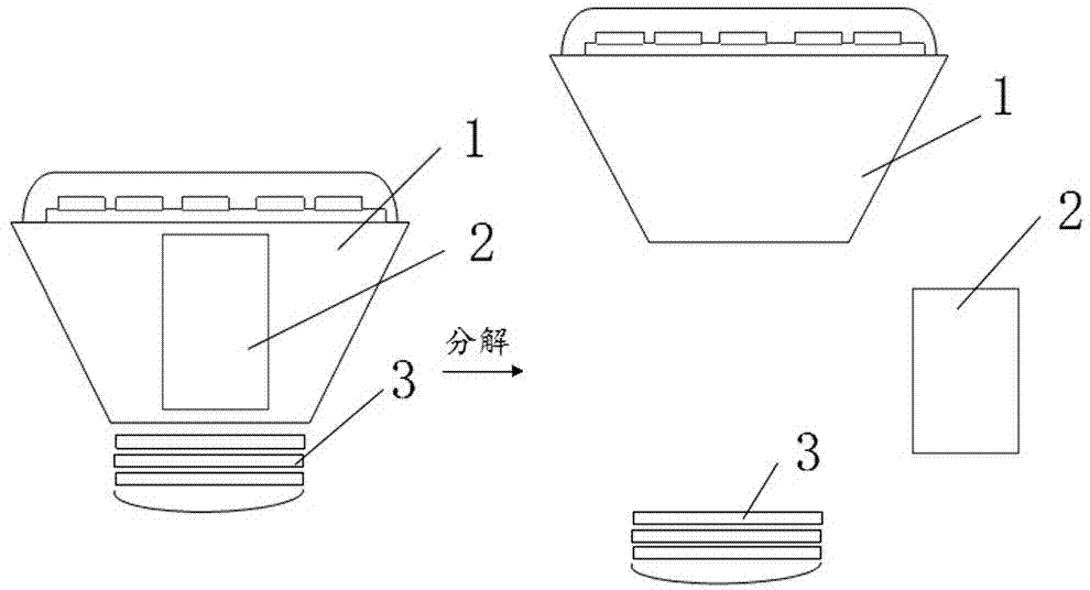
[0027] Example: Decompose the subsystems of a certain brand of 15W LED spotlights, and conduct a reliability accelerated test

[0028] According to different functional modules, the LED lighting system is decomposed into three independent subsystems, which are LED light source subsystem 1 (including modules, heat dissipation and optical components), driving power supply subsystem 2 and assembly interface fixture subsystem. System 3, such as figure 1 shown.

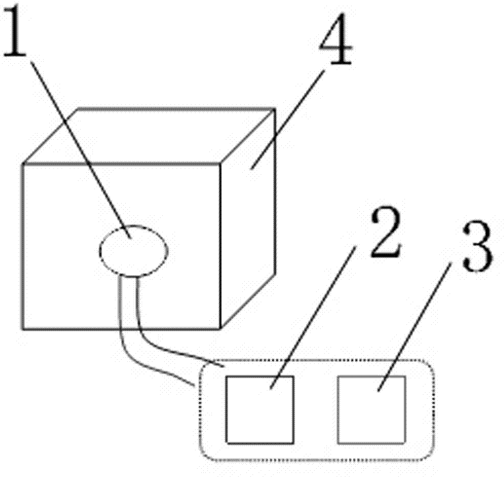
[0029] 1) Use wires to lead out the connection ports at the original electrical connections of the three subsystems to ensure the reliability and ease of use of each connection port, and to ensure the convenience and reliability of subsequent measurement parameters and disassembly;

[0030] 2) First, the LED light source subsystem 1 is used as the target subsystem, and the target subsystem 1 is placed in the accelerated environmental test chamber 4, and the driving power supply subsystem 2 and the assembly interface f...


PUM


Abstract

The invention discloses an accelerated test method of an LED (light-emitting diode) lighting lamp based on subsystem decomposition. The method comprises the steps that: firstly, an LED lamp system is decomposed into a plurality of functionally independent subsystems; next, under precondition that the whole system is maintained to be able to work in a closed state, a target subsystem is placed in an accelerated test environment and is subjected to accelerated reliability test; by utilizing data measurement result obtained in the accelerated test progress, a reliability function of the target subsystem is obtained through extrapolation; and finally, the relevance in performance change of each subsystem and performance change of the whole lamp system is combined, the reliability function of each subsystem is synthesized through application of a system reliability statistical analysis method, then, the reliability function of the whole LED lamp system is obtained through derivation, and reliability evaluation of the whole lamp system is realized. According to the method disclosed by the invention, the complexity, even the infeasibility of an accelerated reliability test directly aiming at the whole lamp system can be avoided; the method not only can be applied to evaluation of accelerated reliability test of the LED lighting lamp, but also can be used as reference for evaluation of the accelerated test of other complicated systems.

Description

technical field [0001] The invention relates to a test method, in particular to an accelerated test method for the reliability of LED lighting fixtures based on subsystem decomposition. Background technique [0002] LED (Light Emitting Diode) is popular because of its long life, no pollution, high efficiency and energy saving. In the field of general lighting, its wide application will be another revolution after the incandescent lamp. However, at this stage, there is a lack of feasible accelerated test methods and standards for the reliability of LED lighting fixtures, which has become a bottleneck restricting LEDs from entering the field of general lighting. [0003] The US Energy Star proposes to conduct at least 6000 hours of room temperature tests on the test samples, but such a requirement is difficult for companies trying to develop efficiently. If the reliability of the product needs to be obtained in a shorter time, it is necessary to use more severe and higher en...

Claims


Application Information

Patent Timeline
Patent Type & Authority Applications(China)
IPC IPC(8): G01R31/44
Inventor 蔡苗杨道国陈文彬梁丽丽龚铭田万春唐红雨贾红亮
Owner GUILIN UNIV OF ELECTRONIC TECH
Why Eureka
Try Eureka