Switch with a testable electricity converter and method for testing an electricity converter

A technology for transformers and switches, applied in the field of current transformers for verifying switches, can solve problems such as switches not working, indistinguishable analysis, and inability to continuously check transducers, etc.

Active Publication Date: 2015-02-18
SIEMENS AG
View PDF6 Cites 0 Cited by
  • Summary
  • Abstract
  • Description
  • Claims
  • Application Information

AI Technical Summary

Problems solved by technology

[0006] In this circuit concept the currents of each individual transducer are analyzed indistinguishably for each channel
From this it is also not possible to determine which transducer input is energized or which is not, especially since in a three-phase current bridge rectifier a balancing current flows between the transducers
[0007] A disadvantage in known power supplies is that the transducer cannot be checked continuously
Failure to identify and report possible damage and thus non-functioning switches so that the plant operator cannot immediately replace the transducer or switch

Method used


Image

  • Switch with a testable electricity converter and method for testing an electricity converter

Examples


Embodiment Construction

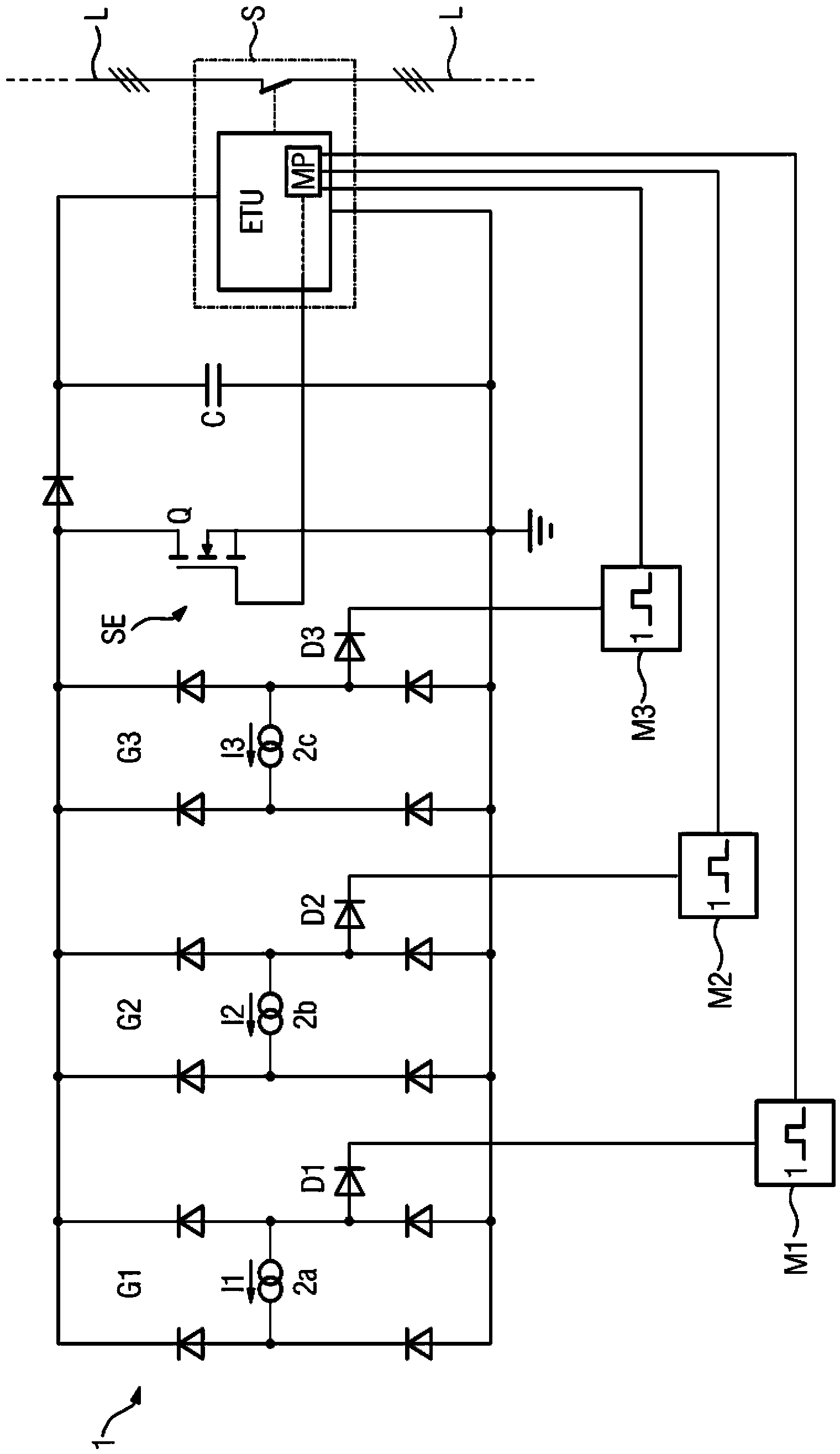
[0015] figure 1 The power supply 1 of the triggering unit ETU of the switch S is shown (shown only schematically) which is a power switch for low voltage. The switch S serves to interrupt the electrical three-phase alternating current I1 , I2 , I3 , wherein all three phase conductors L run through the switch S .

[0016] The switch S is used for distributing current to the electrical switching device and for its protection. The switch S has switching contacts which are separated from each other by a switching mechanism to open the switch S. Air-core coils (Rogowski coils) arranged on conductors L serve as measuring transformers and generate an analog measuring voltage corresponding to the alternating current, wherein the conductors in each case serve as primary windings. Depending on the measured voltage, the switch S is triggered in a parameter-dependent and characteristic-curve-dependent manner in the event of a continuous overload or in the event of a short circuit. The ...


PUM


Abstract

#CMT# # / CMT# The switch (S) has a switching mechanism configured to separate switching contacts to open a switch, a measurement transformer arranged at a conductor and configured to generate an analog measurement voltage corresponding to the alternating current. An input of a monoflop (M1,M2,M3) is connected to a pole of a power converter (2a,2b,2c). The transducer voltage of the monoflop is set such that a predetermined period is provided up to reset of the monoflop and that the level at an output of the monoflop is used for checking the function of the power converter. #CMT# : # / CMT# An independent claim is included for a method for testing a power converter of a power supply of a switch. #CMT#USE : # / CMT# Switch, particularly circuit breaker, for low voltage for interrupting an alternating current flowing through a conductor, and distributing the current in electrical switchgear. #CMT#ADVANTAGE : # / CMT# The switch has an input of a monoflop, which is connected to a pole of a power converter , where transducer voltage of the monoflop is set such that a predetermined period is provided up to reset of the monoflop and that the level at an output of the monoflop is used for checking the function of the power converter, and hence protects electrical switchgear, prevents damage of electrical switchgear, and ensures reliable operation of switch. #CMT#DESCRIPTION OF DRAWINGS : # / CMT# The drawing shows a circuit diagram of a power supply. 1 : Power supply 2a,2b,2c : Power converter D1,D2,D3 : Diodes M1,M2,M3 : Monoflop S : Switch.

Description

technical field [0001] The invention relates to a switch with verifiable current transformers, in particular a power switch for low voltages, and a method for verifying the current transformers of the switch. Background technique [0002] Switches, in particular in the form of low-voltage power switches, are known and serve to interrupt the alternating current flowing through conductors. Switches are used to distribute current to electrical switching devices and for their protection. The switch has switch contacts which are separated from each other by the switch mechanism to open the switch. A current transformer arranged on a conductor in the form of an air-core coil (Rogowski coil, Rogowski spule) serves as a measuring transformer and generates an analog measuring voltage corresponding to the alternating current, the conductor serving as the primary winding. Depending on the measured voltage, in the event of a continuous overload or in the event of a short circuit, the ...

Claims


Application Information

Patent Timeline
Patent Type & Authority Patents(China)
IPC IPC(8): H01H71/22G01R31/327H02H3/08
CPCH02H3/08H02H1/06
Inventor T.德里霍恩G.米勒
Owner SIEMENS AG
Why Eureka
Try Eureka