Vehicle brake device

A technology of braking device and vehicle, which is applied in the direction of braking transmission device, power device, braking action starting device, etc., can solve the problems of high fuel consumption rate and high regeneration efficiency, and achieve the effect of high fuel consumption rate and high regeneration efficiency.

Active Publication Date: 2013-01-23
ADVICS CO LTD
View PDF7 Cites 9 Cited by
  • Summary
  • Abstract
  • Description
  • Claims
  • Application Information

AI Technical Summary

Problems solved by technology

However, when the brake pedal is stepped on quickly, there is a need to apply the basic hydraulic braking force as early as possible compared with high regenerative efficiency and high fuel consumption.

Method used


Image

  • Vehicle brake device
  • Vehicle brake device
  • Vehicle brake device

Examples


Embodiment Construction

[0055] 1) First embodiment

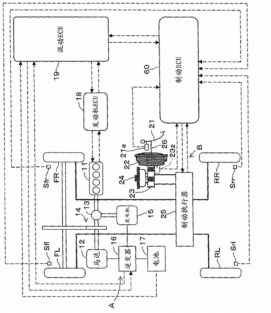
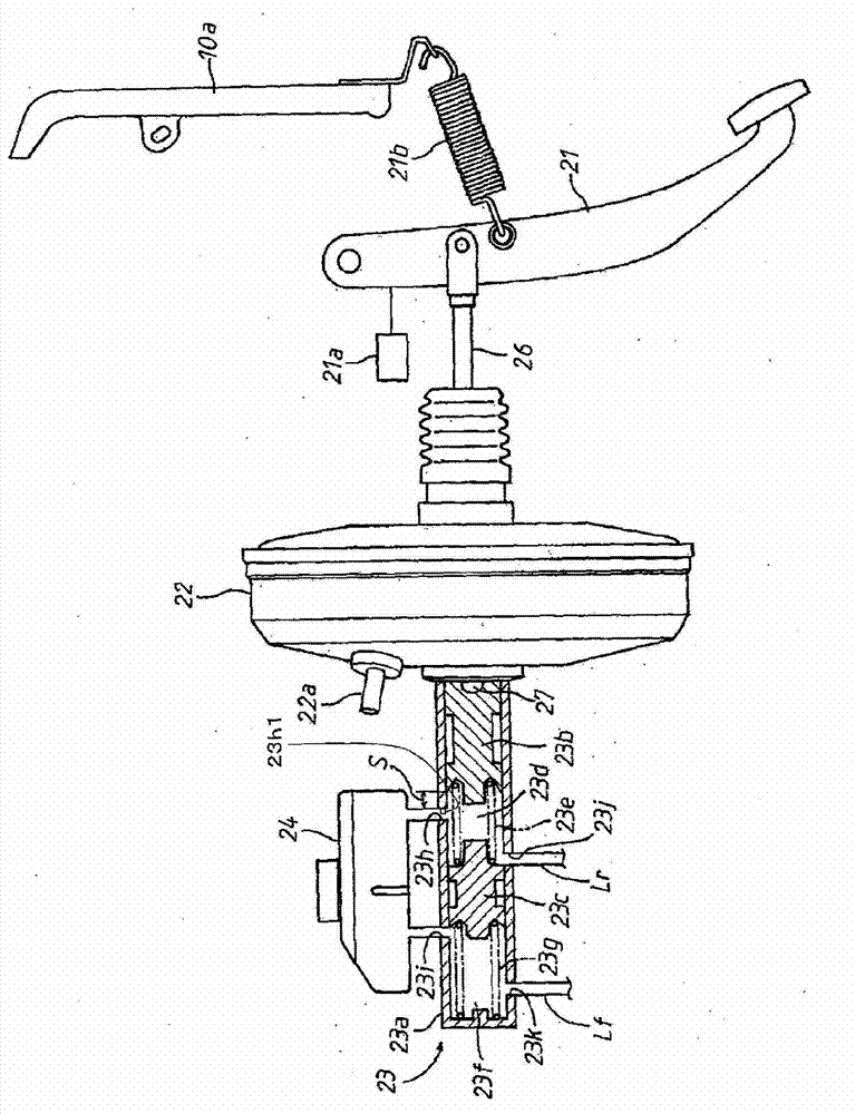
[0056] Hereinafter, a first embodiment in which a vehicle brake device according to the present invention is applied to a hybrid vehicle will be described with reference to the drawings. figure 1 is a schematic diagram showing the structure of the hybrid vehicle, figure 2 It is a schematic diagram showing the configuration of a base hydraulic braking force generating device of a vehicle brake system. like figure 1 As shown, a hybrid vehicle is a vehicle in which drive wheels, for example, left and right front wheels FL and FR are driven by a hybrid system. The hybrid system is a power transmission system that uses two power sources of the engine 11 and the motor 12 in combination. In the case of the first embodiment, it is a parallel hybrid system in which both the engine 11 and the motor 12 are directly driven. In addition, there is a series hybrid system in which the motor 12 drives wheels, and the engine 11 functions as an electric power su...


PUM


Abstract

Disclosed is a vehicle brake device that can achieve high regenerative efficiency and high fuel efficiency as well as apply basic hydraulic braking force as quickly as possible when a brake pedal has been suddenly applied, by proactively utilizing regenerative braking in a low tread force range from when the brake pedal is first pressed until said pedal reaches a predetermined state. The vehicle brake device provides a first port (23h), which connects to a reservoir tank (24) and is provided in a first hydraulic pressure chamber (23d) of a master cylinder (23), between a first position that corresponds to the status at which a blocking end of a first piston (23b) that blocks said port (23h) starts be depressed and a second position that corresponds to a predetermined status that is removed a predetermined distance (S) in the pressure-increase direction of the first piston (23b). An orifice is provided in the first port (23h) that is configured to control the flow of brake fluid from the master cylinder to the reservoir tank when the brake pedal is depressed suddenly and, conversely, to not control said flow when said brake pedal is not depressed suddenly.

Description

technical field [0001] The present invention relates to a braking device for a vehicle, which achieves a target braking force applied to a vehicle by utilizing hydraulic braking force of a hydraulic braking device and regenerative braking force of a regenerative braking device according to a braking operation state. Background technique [0002] Conventionally, as a brake device for a vehicle, a brake device for a vehicle including a hydraulic brake device and a regenerative brake device that passes through a master cylinder in response to depression of a brake pedal is known. A base hydraulic pressure is generated, and the generated base hydraulic pressure is directly applied to the wheel cylinder of each wheel connected to the master cylinder through the oil passage of the interposed hydraulic control valve, thereby generating a base corresponding to the base hydraulic pressure at each wheel. Hydraulic braking force; the regenerative braking device enables regenerative bra...

Claims


Application Information

Patent Timeline
Patent Type & Authority Applications(China)
IPC IPC(8): B60T11/16B60T7/06B60T8/00B60T8/17B60T11/224
CPCB60T1/10Y02T10/6239B60T8/38B60W30/18127B60K6/445B60T2270/604B60W20/00B60W10/188B60T8/4872B60T8/3275B60T13/686B60T7/042B60T2201/03B60T8/4086B60W10/08Y02T10/62B60T13/58B60T7/06
Inventor 牧一哉内藤政行
Owner ADVICS CO LTD
Why Eureka
Try Eureka