
Distance estimation using sound signals

A distance estimation, audio signal technology, applied in the directions of speaker distribution signal, sound wave re-radiation, loudspeaker, etc., can solve the problem that the ranging equipment cannot be located practically, the resolution of the measurement system is reduced, the size of the large audio beam spot, etc. problem, to achieve the effect of improving spatial sound reproduction, accurate spatial perception, and small beam spot size

Active Publication Date: 2013-01-23
KONINK PHILIPS ELECTRONICS NV
View PDF5 Cites 20 Cited by
  • Summary
  • Abstract
  • Description
  • Claims
  • Application Information

AI Technical Summary

Problems solved by technology

[0005] Another problem faced by the use of conventional loudspeaker arrays is that the large aperture required for high directivity also results in a large audio beam spot size which reduces the resolution of the measurement system
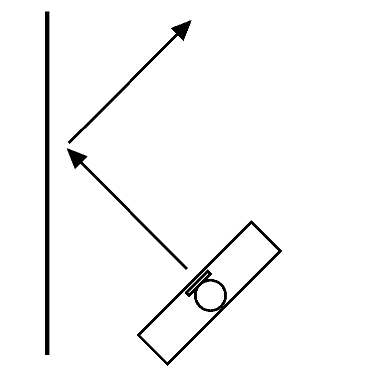
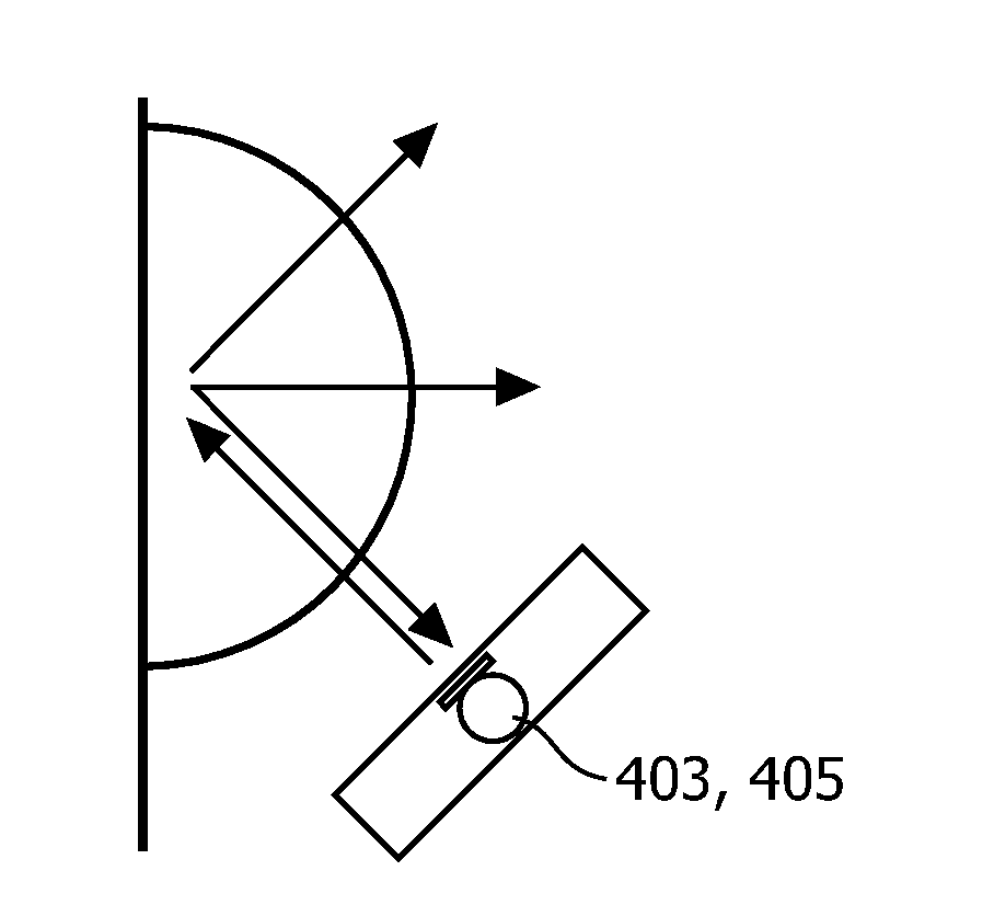
In fact, in many cases even small deviations from the vertical angle lead to measurement signals corresponding to paths with multiple reflections (e.g. more walls), leading to erroneous results and thus e.g. Incorrect calibration of the regenerative system
Such ultrasonic ranging systems are therefore often impractical for many fixed calibration systems where the ranging device cannot be practically located and pointed directly at the object to which the distance is being measured
In particular, these systems tend to require manual operation and are unsuitable for use in many automated systems where the exact position and orientation from the ranging device to the object is not known

Method used


Image

  • Distance estimation using sound signals
  • Distance estimation using sound signals
  • Distance estimation using sound signals

Examples


Embodiment Construction

[0064] The following description focuses on an embodiment of the invention applicable to calibrating a spatial sound reproduction system based on audio environment geometry determined from distance measurements. However, it will be appreciated that the invention is not limited to this application, but may be applied in many other contexts and in many other applications.

[0065] Figure 1 shows a speaker system setup for a conventional five-channel surround sound spatial sound reproduction system, such as a home theater system. The system includes a center speaker 101 providing a center front channel, a left front speaker 103 providing a left front channel, a right front speaker 105 providing a right front channel, a left rear speaker 107 providing a left rear channel, and a right rear speaker 109 providing a right rear channel. The five speakers 101-109 together provide a spatial sound experience at the listening position 111 and allow a listener at this position to experience...


PUM


Abstract

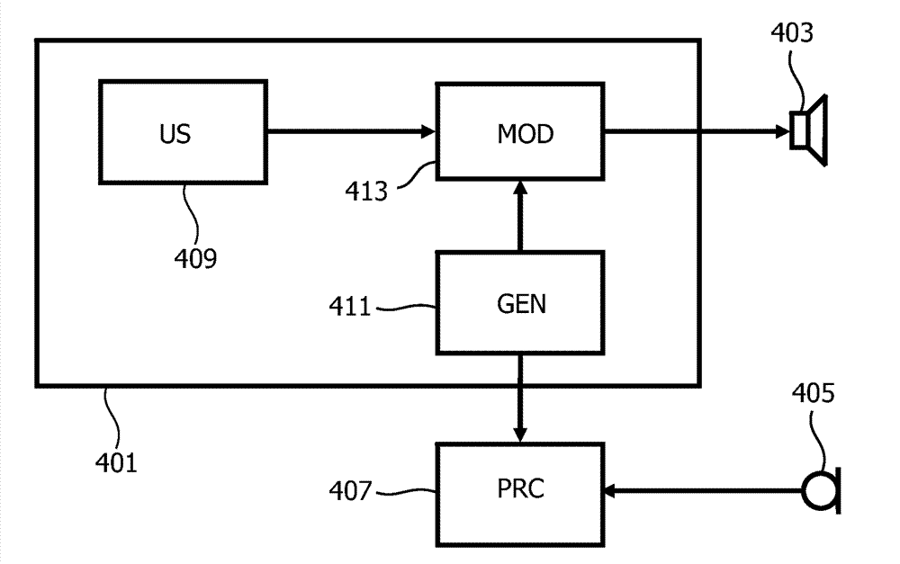
An apparatus comprises a test signal generator (401) which generates an ultrasonic test signal by modulating an audio band test signal on an ultrasonic signal. The ultrasonic test signal is radiated from a parametric loudspeaker (403) and is demodulated by non-linearities in the air. A reflected audio signal may arise from reflections of an object, such as a wall. An audio band sensor (405) generates an audio band captured signal which comprises the demodulated reflected audio band signal. A distance circuit (407) then generates a distance estimate for the distance from the parametric loudspeaker (403) to the object in response to a comparison of the audio band captured signal and the audio band test signal. Specifically two signals may be correlated to determine a delay corresponding to the full path length. Based on the distance estimates an audio environment may be estimated and a sound system may be adapted accordingly.

Description

technical field [0001] The present invention relates to the estimation of distance to objects, and in particular but not exclusively to the characterization of an audio environment based on the estimation of distance. Background technique [0002] Automatic determination of distance is important for many applications. For example, the audio environment greatly affects the performance of loudspeaker systems and, for example, the acoustics of a room significantly affects the spatial experience that can be provided with a spatial sound reproduction system. In order to provide the best possible spatial rendering, it is therefore important that the sound reproduction system is properly calibrated to the specific audio environment. Since it is not possible to account for every possible permutation of room size, sound system position and listener position etc. in advance, it is only possible to provide a limited number of preset options in practice. Proper calibration of the soun...

Claims


Application Information

Patent Timeline
Patent Type & Authority Applications(China)
IPC IPC(8): G01S7/534G01S15/32G01S15/89H04R29/00H04S7/00
CPCG01S7/534G01S15/89G01S7/524G01S15/32H04R3/12H04R2203/12H04R2217/03H04S7/301
Inventor W.J.兰布R.M.亚尔特斯
Owner KONINK PHILIPS ELECTRONICS NV
Learn More