Stable rolling control device

A control device and stable technology, applied in the direction of rolling mill control device, metal rolling, metal rolling, etc., can solve the problems of material surface damage, poor roughness, out-of-tolerance strip side bending, etc., to improve the surface roughness , The effect of rolling stability and easy control

Inactive Publication Date: 2013-01-30
上海格林赛高新材料有限公司
View PDF4 Cites 4 Cited by
  • Summary
  • Abstract
  • Description
  • Claims
  • Application Information

AI Technical Summary

Problems solved by technology

[0007] 2. The local surface of the material is damaged, and the roughness is out of tolerance.
[0008] 3. The size of the thin material at the junction of th...

Method used


Image

  • Stable rolling control device
  • Stable rolling control device
  • Stable rolling control device

Examples


Embodiment Construction

[0024] The following are embodiments made according to the technical solution of the present invention in conjunction with the accompanying drawings to further illustrate the present invention.

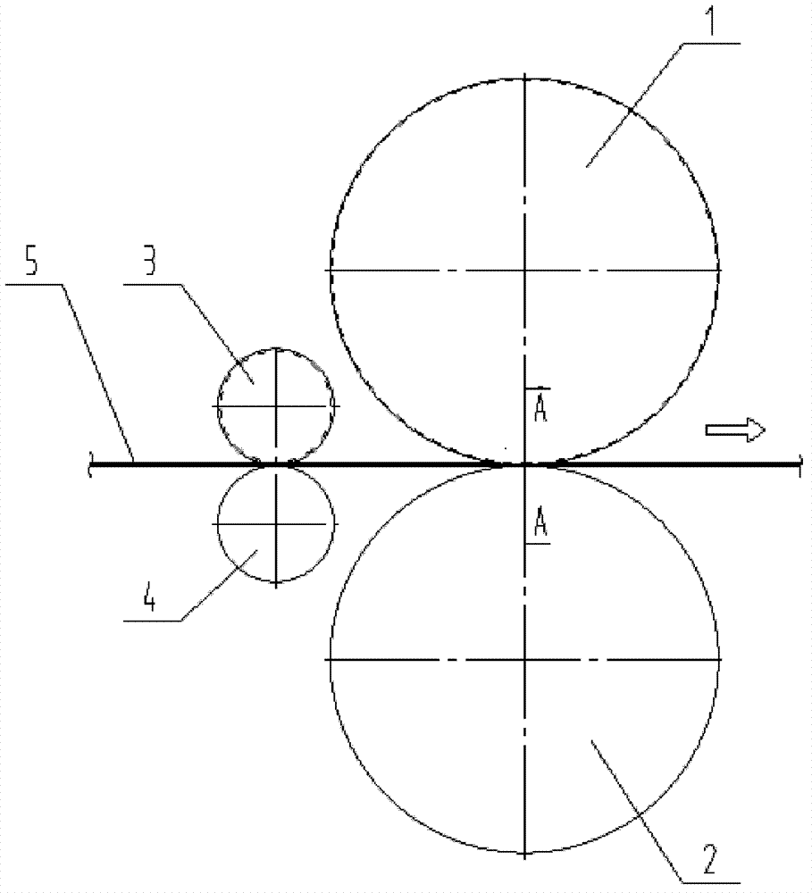
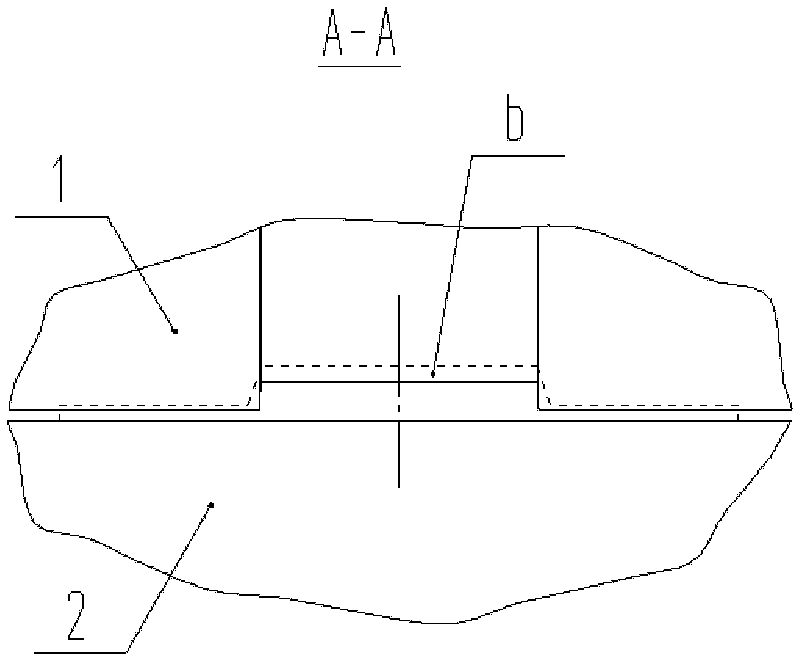
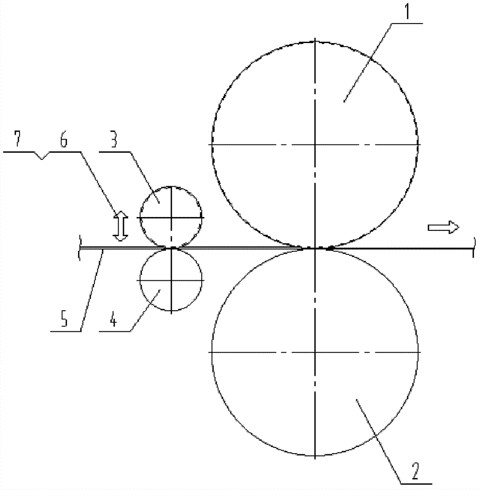
[0025] see Figure 7 In c, the thin material thickness of the finished T-shaped strip is t1=0.38mm, the thick material thickness T1=1.27mm, A1=27mm, α≤5 0 , B1=65.8mm, Figure 7 In d, the thickness of the thin material with blank t2=0.53mm, the thickness of the thick material T2=1.77mm, A1=27mm, α≤5 0 , B1=76mm, pass roll diameter d=200mm, guide roll diameter d=60mm, see image 3 When the belt is threaded, the guide position is in a horizontal position. When rolling, the guide position is gradually raised by the guide position lifting device, and tension is generated to make the trapezoidal convex part of the strip and the groove hole of the pass roll 1 form a tightly fitting arc Segment (see Figure 4 , 5 ), the guide level adjustment device is used to adjust the center of the strip blank...


PUM


Abstract

The invention relates to a stable rolling control device. The purpose of the stable rolling control device can be achieved by the technical scheme which includes that a guide device is lifted step by step during rolling and produces tension to enable a strip billet trapezoidal projection and a groove type hole of a hole type roll 1 to form a clinging segmental arc (see figures 4 and 5), a horizontal guide adjustment device 7 is used for horizontal micro-adjustment of alignment of the strip billet center and the roll pass center, left-right movement of a strip billet is quite effectively controlled as the trapezoidal projection and the groove type hole of the hole type roll 1 form the clinging segmental arc which is close to a rolling area. Additionally, the size A1 and the angle alpha of the strip billet trapezoidal projection are as same as those of a finished product trapezoidal projection, so that factors caused by excessive local machining rate at junctions of thick materials and thin materials are avoided, and rolling is stable and reliable.

Description

Technical field [0001] The invention relates to a control device for stable rolling of strips, in particular to a control device for stable rolling of special-shaped cross-section strips. Background technique [0002] The profile of the profiled copper alloy strip, which is used as the lead frame material of the power tube in the semiconductor discrete device, is usually formed in two specifications: thin and thick. The thin material is the lead wire for circuit connection, and the thick material supports the chip and heat dissipation. Image 6 The middle a is a T-shaped section, the thick material in the middle is a trapezoidal protrusion, and the two sides are thin materials of equal size. In order to meet the requirements of high-speed punching die for frame punching, the dimensional tolerance and side bending of the special-shaped strip , The residual internal stress has very strict technical requirements. The processing of special-shaped strips is generally divided into two pr...

Claims


Application Information

Patent Timeline
IPC IPC(8): B21B37/68
Inventor 杨惟志余波
Owner 上海格林赛高新材料有限公司
Why Eureka
Try Eureka