
Composite clamping device for rows of pipes

A technology of clamping device and knife device, which is applied in the field of composite clamping device for row pipes, can solve the problems of no saw blade holder, unstable quality of sawing section, vertical clamping and jamming, etc., so as to improve the quality of sawing section , Protect the quality of the saw cut surface, and the effect of stable and reliable action

Inactive Publication Date: 2013-01-30
CHINA NAT HEAVY MACHINERY RES INSTCO
View PDF9 Cites 11 Cited by
  • Summary
  • Abstract
  • Description
  • Claims
  • Application Information

AI Technical Summary

Problems solved by technology

[0002] The horizontal clamping of the traditional clamping device adopts hydraulic synchronization, which is easy to cause the center of the clamped pipe and the center of the saw blade to deviate
Two oil cylinders are used for vertical clamping, and hydraulic synchronization is also adopted, which may easily cause vertical clamping jamming
At the same time, it does not have the function of clamping and letting the knife out. When the saw blade is lifted, it is easy to scratch the section, and there is no saw blade holder, so the quality of the saw section is unstable.
Vertical clamping and horizontal clamping are not installed in a box, the structure is huge and difficult to install, and the clamped material head is long and the yield is low.

Method used


Image

  • Composite clamping device for rows of pipes
  • Composite clamping device for rows of pipes

Examples


Embodiment Construction

[0016] The structural principle and working principle of the present invention will be described in detail below in conjunction with the accompanying drawings.

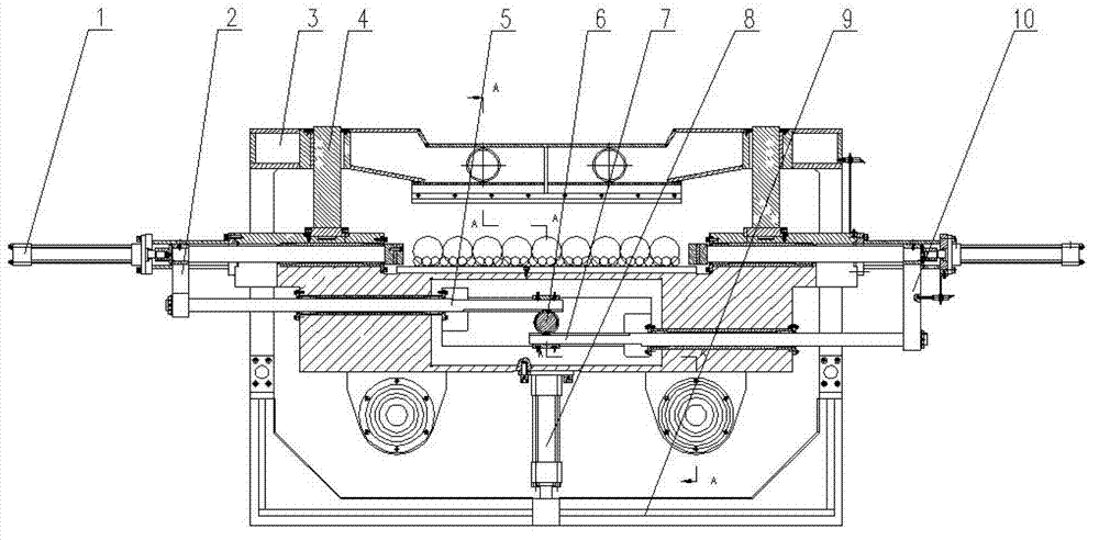
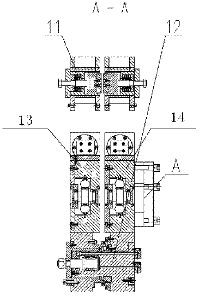
[0017] refer to figure 1 , figure 2 , a composite clamping device for row pipes, including a fixed clamping device 14 and a floating clamping device 13 with the same structure, the side connected to the host is the fixed clamping device 14, and the outer one is called the floating clamping device 13, The floating clamping device 13 and the fixed clamping device 14 are connected together through the piston rod of the knife device 12. The fixed clamping device 14 includes horizontal clamping oil cylinders 1 fixed on both sides of the box, and two horizontal clamping The first connecting rod 2 and the second connecting rod 10 of the oil cylinder 1 are respectively connected with the corresponding first synchronizing rack 5 and the second synchronizing rack 7, and the first connecting rod 2 and the second connecting rod...


PUM


Abstract

The invention relates to a composite clamping device for rows of pipes. The composite clamping device comprises a fixed clamping device and a floating clamping device which have the same structure, wherein the floating clamping device and the fixed clamping device are connected through a tool retracting device; the fixed clamping device comprises horizontal clamping oil cylinders fixed on the two sides of a box; the two horizontal clamping oil cylinders are connected with synchronous racks through connecting rods; the connecting rods are meshed with a synchronous gear on the upper and lower sides; a vertical clamping device slidably connected with vertical guide posts is arranged over the box; the vertical guide posts are fixed on the box; a vertical clamping oil cylinder is fixed under the box; the vertical clamping oil cylinder and the vertical clamping device are connected to a vertical connecting frame; and saw blade retainers and the tool retracting device are arranged on the vertical clamping device. Rows of steel pipes can be horizontally and vertically clamped, the stability of the lower half part of a saw blade is kept by the saw blade retainers, and the composite clamping device has the advantages of simple and compact structure, good clamping effect, capability of retracting a tool and realizing automatic control, and the like.

Description

technical field [0001] The invention relates to a clamping device used in steel pipe gang sawing machines and other occasions where compound clamping is required for sawing, in particular to a compound clamping device for pipe arrangement. Background technique [0002] The horizontal clamping of the traditional clamping device adopts hydraulic synchronization, which is easy to cause the center of the clamped pipe and the center of the saw blade to deviate. Two oil cylinders are used for vertical clamping, and hydraulic synchronization is also adopted, which may easily cause vertical clamping jamming. At the same time, it does not have the function of clamping and letting the knife. When the saw blade is lifted, it is easy to scratch the section, and there is no saw blade holder, so the quality of the saw section is unstable. Vertical clamping and horizontal clamping are not installed in a box, the structure is huge and difficult to install, and the clamped material head is ...

Claims


Application Information

Patent Timeline
Patent Type & Authority Applications(China)
IPC IPC(8): B23Q3/08
Inventor 姚赟张超解吉辉孙丽丽刘录锋杨晓东郝瑾郝乐
Owner CHINA NAT HEAVY MACHINERY RES INSTCO
Learn More