Inside engaged gear pump or gear motor device with multilayer structure

A technology of internal meshing gear pumps and gear motors, applied to pumps, rotary piston pumps, rotary or swinging piston engines, etc., can solve the problems of manufacturing difficulty and manufacturing cost, increased internal leakage of the device, and failure of device functions, etc., to achieve Reduce processing difficulty and manufacturing cost, improve contact sealing state, and prolong service life

Inactive Publication Date: 2013-01-30
李庆中
View PDF7 Cites 5 Cited by
  • Summary
  • Abstract
  • Description
  • Claims
  • Application Information

AI Technical Summary

Problems solved by technology

Therefore, the machining accuracy requirements for cycloidal gears are high, and small machining errors may lead to assembly failure or uneven load
[0007] The existing internal meshing gear pump relies on the contact accuracy between the inner and outer rotor tooth surfaces to ensure the sealing of each cavity. Due to the sliding friction between the inner and outer rotor tooth surfaces, under normal circumstances, when the inner and outer rotor tooth surfaces are worn, it will Increase the internal leakage of this type of device, which will cause the device to fail and be scrapped. In order to prolong the service life of the pump, it is usually solved by improving the precision of the parts and the surface hardness of the inner and outer rotor materials, so that its manufacturing difficulty and manufacturing cost will be greatly increased.

Method used


Image

  • Inside engaged gear pump or gear motor device with multilayer structure
  • Inside engaged gear pump or gear motor device with multilayer structure
  • Inside engaged gear pump or gear motor device with multilayer structure

Examples


Embodiment 1

[0034] Embodiment 1 (n=1)

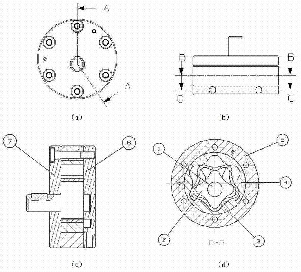
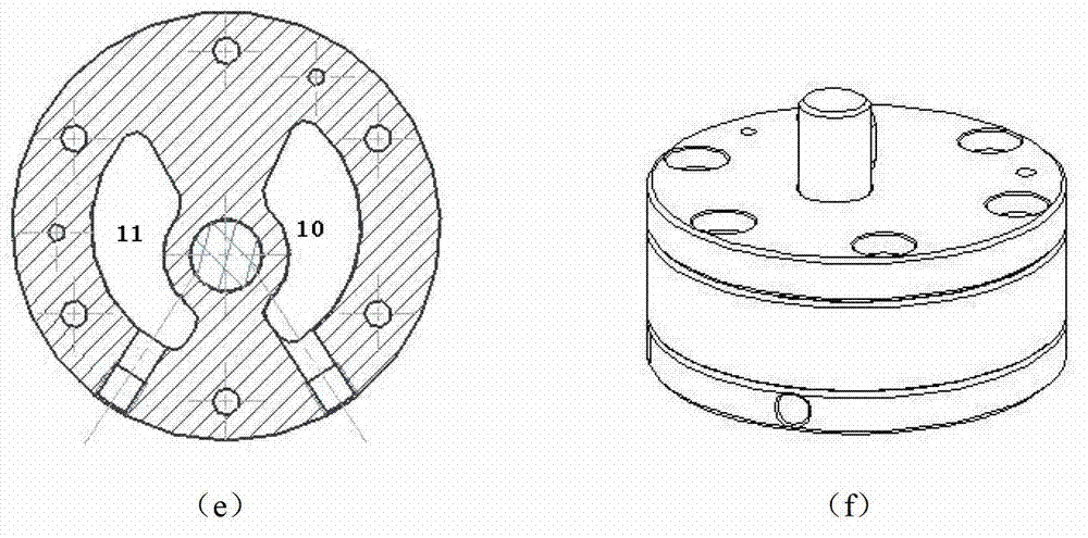
[0035] see figure 2 a to figure 2 As shown in f, in Embodiment 1 of the present invention, the multi-layer internal gear pump includes a shaft 1, an inner rotor 2, a double-sided toothed ring sleeve 3, an outer rotor 4, a pump body 5, a rear cover 6 and The front cover 7; the number of teeth of the inner and outer rotors and the double-sided toothed ring sleeve is equal to 1; in this embodiment, the number of teeth of the inner rotor 2 is 1 less than that of the double-sided toothed ring sleeve 3, and the number of teeth of the double-sided toothed ring sleeve 3 is less than that of the outer rotor 4. The number of teeth is less 1; the tooth profile of the inner rotor 2, the double-sided toothed ring sleeve 3 and the outer rotor 4 adopts a cycloid tooth profile design. In this embodiment, the numbers of teeth of the inner rotor 2 , the double-sided toothed collar 3 and the outer rotor 4 are 4, 5, and 6, respectively.

[0036] In this embodiment...

Embodiment 2

[0037] Embodiment 2 (n>1)

[0038] see image 3 As shown, in Embodiment 2 of the present invention, the internal meshing gear pump of this multi-layer structure includes a shaft 1, an inner rotor 2, a double-sided toothed ring sleeve 3, an outer rotor 4, a pump body 5, a rear cover 6, a front Cover 7, the first crescent partition 8 and the second crescent partition 9; the difference between the number of teeth of the inner and outer rotors and the double-sided tooth ring sleeve 3 is greater than 1 (also known as the multi-tooth difference structure); in this embodiment, the inner rotor 2 The number of teeth of the double-sided toothed collar 3 is 4 less than that of the double-sided toothed collar 3, and the number of teeth of the double-sided toothed collar 3 is 4 less than that of the outer rotor 4; Open profile, cycloid profile or other profile designs. In this embodiment, the numbers of teeth of the inner rotor 2 , the double-sided toothed collar 3 and the outer rotor 4 ...

Embodiment 3

[0041] see Figure 4 As shown, in the third embodiment of the present invention, the difference between the internal gear pump with multi-layer structure and the first embodiment is that the difference in the number of teeth between the inner rotor 2 and the toothed collar 3 is equal to 1, and the outer rotor 4 The difference between the number of teeth and the toothed ring sleeve 3 is greater than 1; the inner rotor 2, the double-sided toothed ring sleeve 3 and the outer rotor 4 can adopt cycloid tooth profile design, and the structural part with a tooth difference greater than 1 can also use involute teeth outline design. In this embodiment, the numbers of teeth of the inner rotor 2 , the double-sided toothed collar 3 and the outer rotor 4 are 4, 5, and 8, respectively. According to the third scheme, the inner rotor 2, the double-sided toothed ring sleeve 3, the crescent partition 8 and the outer rotor 4 are installed in the pump body 5 from the inside to the outside in seq...


PUM


Abstract

The invention relates to an inside engaged gear pump or gear motor device with a multilayer structure. The device comprises an inner rotor, N layers of double-faced toothed ring sleeves, an outer rotor and a pump body, wherein N is a positive integer more than or equal to 1; the inner rotor, the double-faced toothed ring sleeves and the outer rotor are sequentially arranged in the pump body from inside to outside; the tooth faces of the inner rotor, the N layers of double-faced toothed ring sleeves and the outer rotor are in a mutual contact engaged state; at least two sealed accommodation cavities are formed between adjacent elements of the inner rotor, the N layers of double-faced toothed ring sleeves and the outer rotor; and rotating axes of the inner rotor, the N layers of double-faced toothed ring sleeves and the outer rotor are positioned in the same plane, and are not overlapped. The double-faced toothed ring sleeves are additionally arranged between the inner rotor and the outer rotor, so that a volume between the rotor can be multiplied under the condition of no increase of widths of the rotors; and by the elastic compensation function of the double-faced toothed ring sleeves, a requirement on the machining accuracy of the inner and outer rotors of the device can also be lowered, so that machining difficulty and maintenance cost are lowered.

Description

【Technical field】 [0001] The present invention relates to a hydraulic pump or hydraulic motor device for industrial equipment or machinery, in particular to an internal gear pump or gear motor device. 【Background technique】 [0002] A hydraulic pump is an energy conversion device in a hydraulic transmission system. It converts the mechanical energy transmitted by power machinery (such as electric motors, internal combustion engines, etc.) It is the power source of the hydraulic system. [0003] A hydraulic motor traditionally refers to an energy conversion device that outputs rotational motion and converts the hydraulic energy provided by the hydraulic pump into mechanical energy. From the point of view of energy conversion, hydraulic pumps and hydraulic motors are reversible hydraulic components. Inputting working fluid to any hydraulic pump can make it a hydraulic motor; on the contrary, when the main shaft of the hydraulic motor is driven by the external When the torqu...

Claims


Application Information

Patent Timeline
Patent Type & Authority Applications(China)
IPC IPC(8): F04C2/10F03C2/08
Inventor 李萌李庆中
Owner 李庆中
Why Eureka
Try Eureka