Double-flange cylinder spring gear pump

A technology of cylindrical springs and gear pumps, applied to pumps, pump components, rotary piston pumps, etc., can solve the problems of force and asymmetry of gear pumps that have not been seen, and achieve completely symmetrical and uniform wear and novel ideas.

Active Publication Date: 2013-01-30
苏州盛泽科技创业园发展有限公司
View PDF12 Cites 2 Cited by
  • Summary
  • Abstract
  • Description
  • Claims
  • Application Information

AI Technical Summary

Problems solved by technology

my country patent authorization announcement number: CN1059019C swing vane pump; my country patent authorization announcement number: CN100374725C rotary vane pump; The internal gear pump of plastic casing; my country's patent authorization announcement number: CN101120175B and my country's patent authorization announcement number: CN101403382B a kind of gear pump for micro-miniature turbojet engine, etc., all do not see that there is a practical method to solve the stress of the gear pump. Symmetry and face wear clearance control issues

Method used


Image

  • Double-flange cylinder spring gear pump
  • Double-flange cylinder spring gear pump
  • Double-flange cylinder spring gear pump

Examples


Embodiment Construction

[0020] In conjunction with the accompanying drawings and embodiments, the structure and working principle of the present invention are further described in detail:

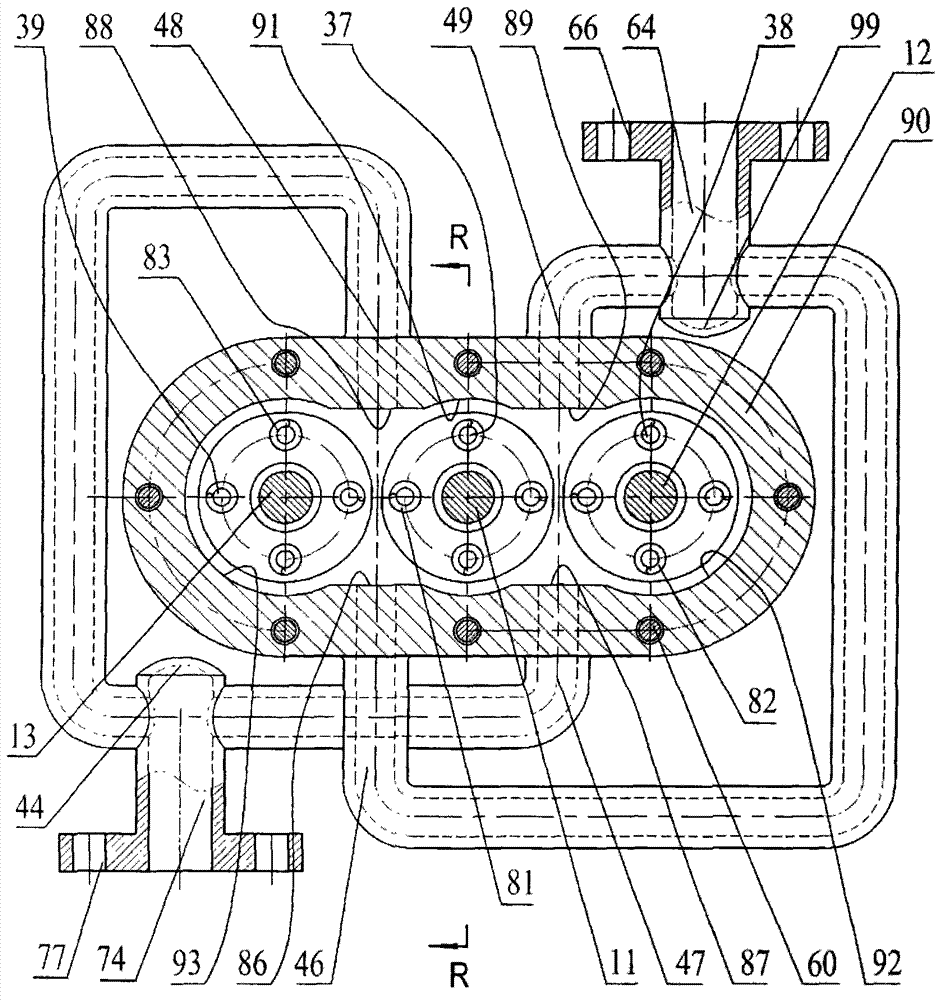
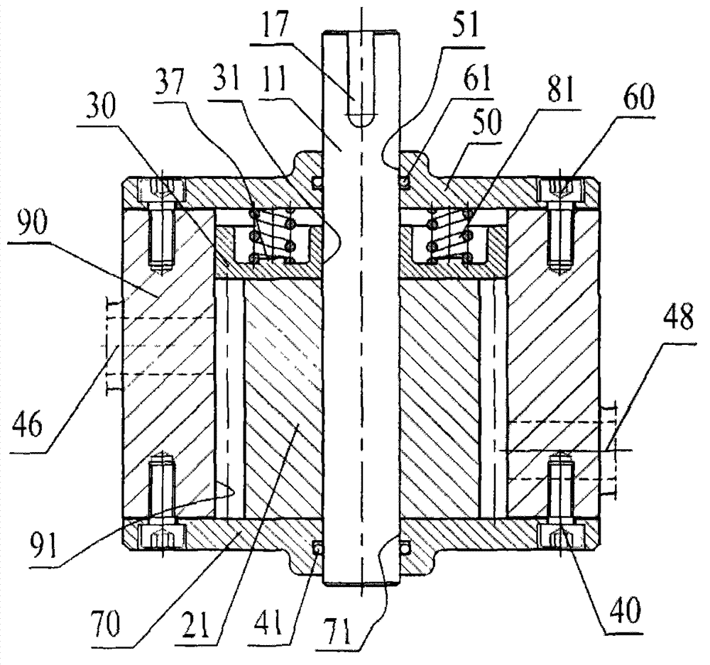
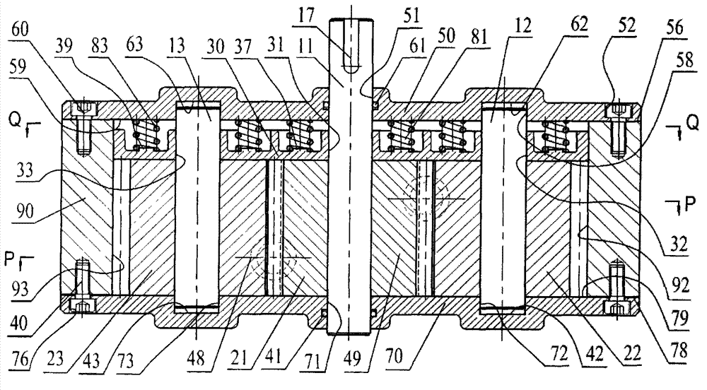
[0021] exist figure 1 , figure 2 , image 3 , Figure 4 and Figure 5 Among them, a double-flange cylindrical spring gear pump, the three-axis oil pump is externally connected with a right inlet pipeline 47 and a left inlet pipeline 48, as well as a right outlet pipeline 49 and a left outlet pipeline 46, as an improvement: the right inlet pipeline The road 47 and the left inlet pipeline 48 are collected into the oil inlet manifold 74 with the inlet flange 77; the right outlet pipeline 49 and the left outlet pipeline 46 are collected into the oil outlet with the outlet flange 66 In the main pipe 64; the three-axis oil pump includes a driving shaft 11, a right driven shaft 12, a left driven shaft 13, a main gear 21, a right slave gear 22, a left slave gear 23, a front outer end cover 50, and a rear outer end C...


PUM


Abstract

The invention relates to a double-flange cylinder spring gear pump. A left inlet pipeline and a right inlet pipeline are converged into an oil inlet header pipe provided with an inlet pipe flange; a left outlet pipeline and a right outlet pipeline are converged into an oil outlet header pipe provided with an outlet pipe flange; two arcs at the center of the inner cavity of a pump body and the excircle of a driving gear are in sliding fit, and the right large semicircle of the inner cavity of the pump body and the excircle of a right driven gear are in sliding fit; a driving shaft at the center of a driving gear and a right driven shaft at the center of the right driven gear are parallel to each other, the driving shaft at the center of the driving gear and a left driven shaft at the center of the left driven gear are parallel to each other; the inner plane of the rear cover of a rear outer end cap is tightly fixed on the rear end face of the pump body; the inner plane of the front cover of a front outer end cover is tightly fixed on the front end face of the pump body; and the frontal plane of an end face compensating disc is attached to the driving gear, the right driven gear and the left driven gear, and a middle cylinder spring, a right cylinder spring and a left cylinder spring are respectively arranged between the back of the end face compensating disc and the inner plane of the front outer end face.

Description

technical field [0001] The invention belongs to the field of mechanical engineering. The international patent classification is F04D non-variable displacement pump, which relates to an energy conversion rotary positive displacement pump which converts mechanical energy into liquid pressure energy, in particular to a double-flange cylindrical spring gear pump. Background technique [0002] The known gear pumps are all working in pairs. Due to the large pressure difference between the inlet and outlet, it is bound to cause unilateral force on the gear, especially the unilateral force on the driving gear, which directly causes unilateral wear and leakage at the shaft of the driving gear. As a result, the life of the gear pump is short and the pressure rise is limited. Another problem that has been plagued by gear pumps that cannot be effectively solved is that after long-term high-speed operation, the inevitable wear of the end face cannot be effectively compensated. my countr...

Claims


Application Information

Patent Timeline
Patent Type & Authority Applications(China)
IPC IPC(8): F04C2/18F04C15/00
Inventor 张意立
Owner 苏州盛泽科技创业园发展有限公司
Why Eureka
Try Eureka