Cross-flow fan

A cross-flow fan and cross-flow wind wheel technology, which is applied in the direction of mechanical equipment, radial flow pumps, machines/engines, etc., can solve problems such as poor flow field characteristics, large gap between the wind wheel and the volute, and unstable flow field

Active Publication Date: 2013-01-30
GREE ELECTRIC APPLIANCES INC
View PDF7 Cites 18 Cited by
  • Summary
  • Abstract
  • Description
  • Claims
  • Application Information

AI Technical Summary

Problems solved by technology

[0003] Chinese Patent Document No. CN101000158A discloses an indoor unit structure of a ceiling type split air conditioner, which adopts a V-shaped evaporator, and the acute angle between the two evaporators and the vertical direction is 45°, which increases the heat transfer. The area of ​​the evaporator reduces the length of the evaporator and the space occupied by the evaporator, but in the vertical direction of the center of the wind wheel, the angle of α is 75°, and the gap between the wind wheel and the vo

Method used


Image

  • Cross-flow fan
  • Cross-flow fan
  • Cross-flow fan

Examples


specific Embodiment 1

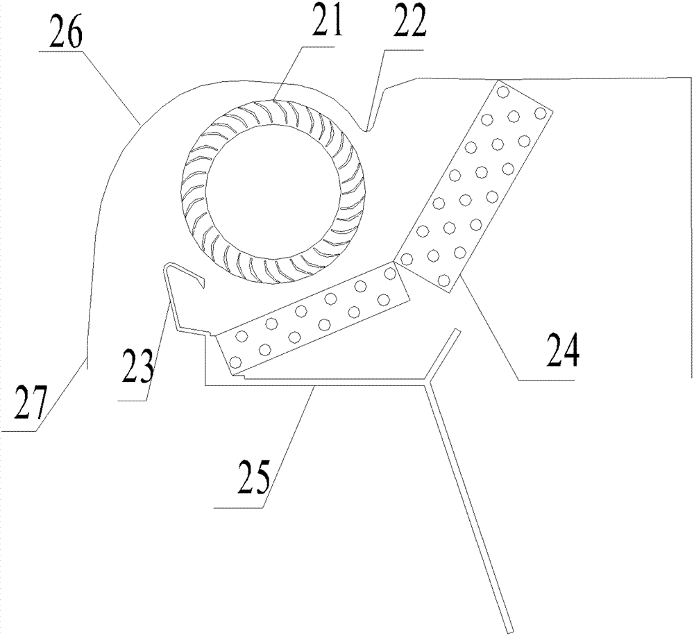
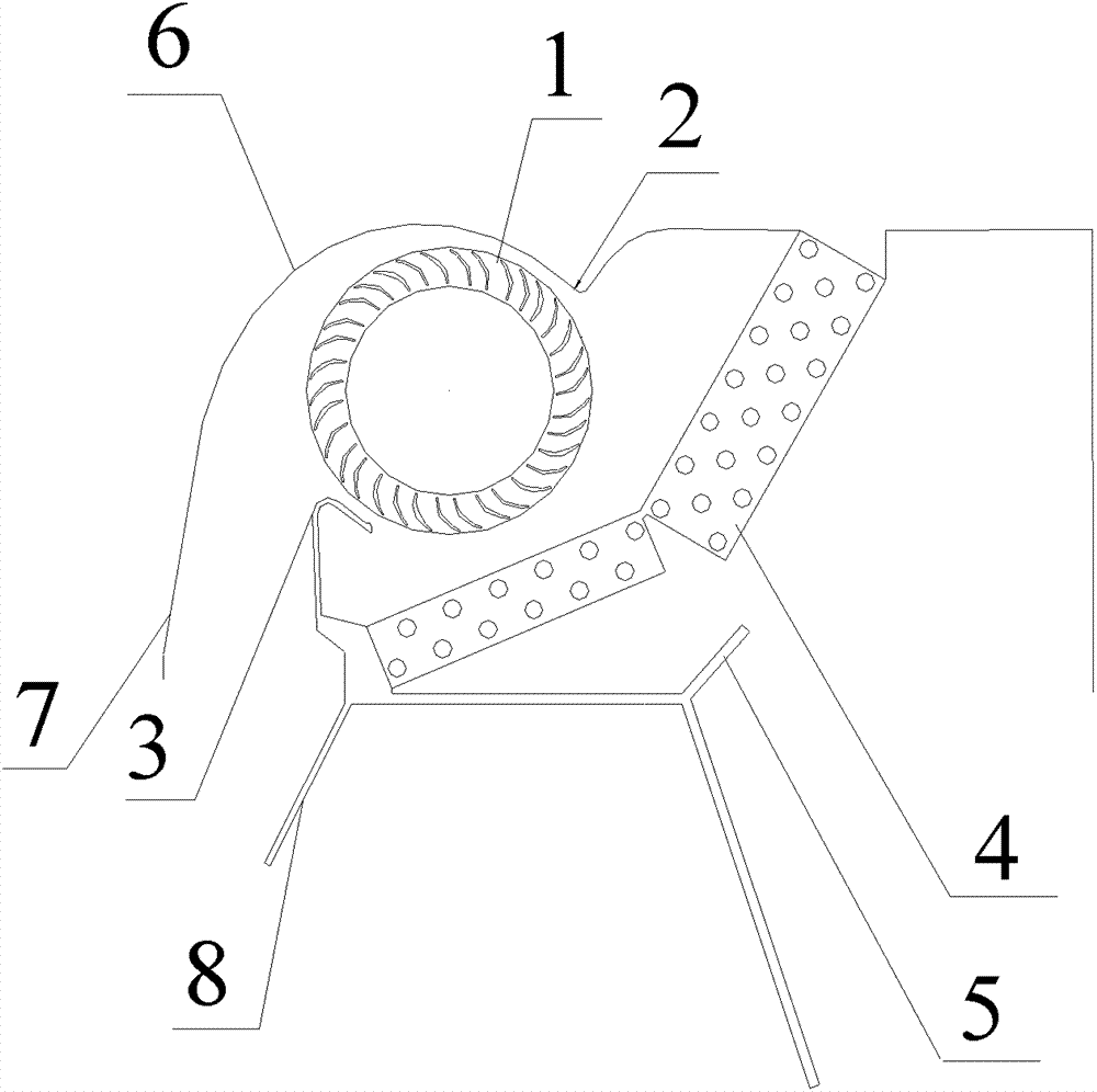
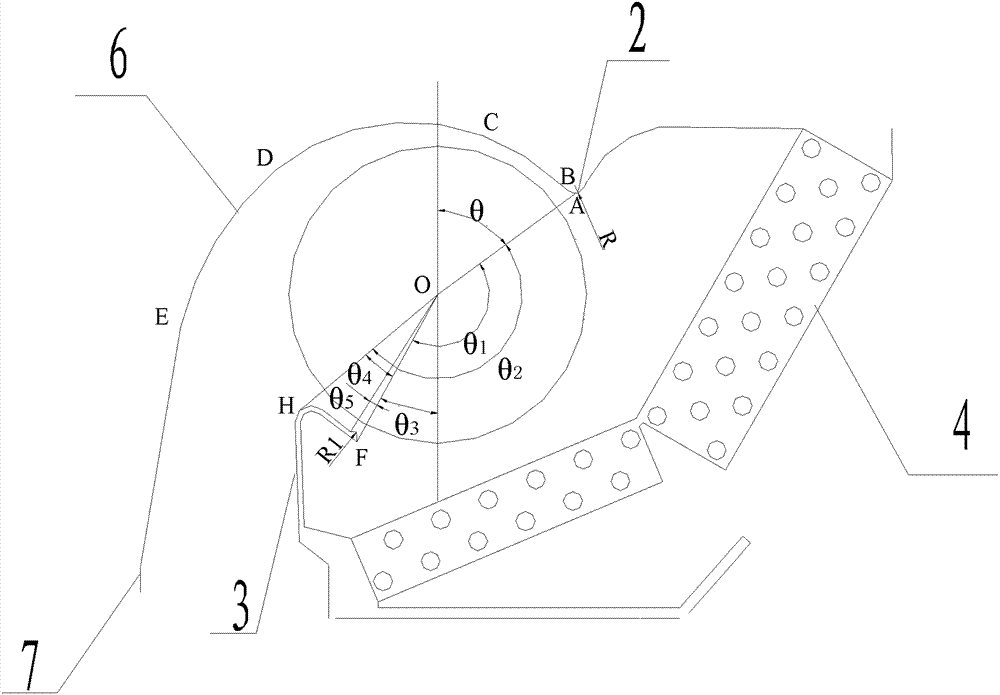
[0032] Such as Figure 3-4 As shown, the structural parameters of this embodiment mainly include the following points, the tangent point between the sectional curve of the rear volute tongue 2 and the horizontal plane is point A, and the end point of the sectional curve of the front volute tongue 3 near the end of the air inlet is point F, Through the central point O of the cross-flow wind wheel 1, a tangent line that is tangent to the cross-sectional curve of the front volute tongue 3 intersects the cross-sectional curve of the front volute tongue 3 at point H, and the point A and the center vertical line of the cross-flow wind wheel 1 have The included angle θ=45°, the radius of curvature R=2.76mm of the section curve of the rear cochlear tongue 2. Angle θ between point A and point F with ∠AOF 1 =155°, the included angle θ of ∠AOH between point A and point H 2 =176°.

[0033] The angle θ between the line connecting the terminal point F of the anterior cochlear tongue 3 an...

specific Embodiment 2

[0038] Such as Figure 3-4 As shown, the structural parameters of this embodiment on the basis of Embodiment 1 have the following changes: the included angle θ=50° between the point A at the rear volute tongue 2 and the vertical line of the center of the cross-flow wind wheel 1, and the rear The radius of curvature R of the section curve of the volute tongue 2 is 3.49mm, and the included angle θ between point A and point H is ∠AOH 2 =177°; ∠BOA angle θ between the end point B and point A of the BC curve section near the air inlet side 6 =5°; the radius of curvature R of the boss 1 = 1.2 mm.

[0039] The CFD simulation speed vector diagram of the present embodiment is Figure 7 , the velocity distribution of the flow field is marked in the form of contour lines in the figure, and the number marks represent the flow velocity. It can be seen that the flow field is similar to that of Example 1, but the scale of the eccentric worm is relatively smaller than that of the prior art...

specific Embodiment 3

[0040] Such as Figure 3-4 As shown, the structural parameters of this embodiment have the following changes on the basis of Embodiment 1. The included angle θ=55° between the point A at the 2 points of the rear volute tongue and the vertical line of the center of the cross-flow wind wheel 1 is 55°. The curvature radius R of the volute tongue 2 section curve is 5.27mm, and the AOH angle θ between point A and point H 2 =177°; ∠BOA angle θ between the end point B and point A of the BC curve section near the air inlet side 6 =5°; the radius of curvature R of the boss 1 = 1.15 mm.

[0041] The CFD simulation speed vector diagram of the present embodiment is Figure 8 , the velocity distribution of the flow field is marked in the form of contour lines in the figure, and the numerical marks represent the flow velocity. It can be seen that the scale of the eccentric worm is relatively smaller, the effective flow area of ​​the cross-flow rotor 1 is increased, and the flow field at ...


PUM


Abstract

The invention provides a cross-flow fan which comprises a cross-flow wind wheel, a chassis volute, an evaporator, a front volute tongue and a water receiving disc, wherein the chassis volute is provided with a curved inner surface, is covered on the outer side of the cross-flow wind wheel, and comprises a wind outlet section, a wind inlet section and a rear volute tongue; the wind inlet and the wind outlet both extend downward; the wind outlet side of the water receiving disc is also provided with a wind outlet guide plate extending downward from the lower direction of the front volute tongue; the wind outlet guide plate and the longitudinal wall of the front volute form a wind guide angle; and the tangential point of the cross section curve of the rear volute tongue and the water level is a point A, and an included angle formed between the connecting line of the point A and the central point of the cross-flow wind wheel and a vertical line passing through the central point O of the cross-flow wind wheel is theta, and theta is greater than or equal to 45 degrees and less than or equal to 55 degrees. The cross-flow fan provided by the invention has an optimized air channel structure, is high in wind rate, and is low in noise.

Description

technical field [0001] The invention relates to a cross-flow fan, in particular to a cross-flow fan which can be used for both embedded and ceiling-mounted air conditioners. Background technique [0002] The cross-flow fan has the characteristics of high outlet dynamic pressure, long blowing distance, flat and uniform air flow, slender and compact structure, and low noise. It is widely used in air purification and dust removal, ventilation, automobiles, air conditioners and many household appliances. With the improvement of people's living standards, the requirements for the comfort of the acoustic environment for work and life are also constantly increasing, especially because of the aesthetics of the house structure and decoration, higher requirements are put forward for the noise and installation of air conditioners. Traditional embedded or ceiling-mounted air conditioner indoor units use centrifugal fans with high speed and high noise and vibration. Therefore, the embed...

Claims


Application Information

Patent Timeline
IPC IPC(8): F04D17/04F04D29/42
Inventor 王雄治陈民华叶容君肖忠弟董术海赵伟东余锐生
Owner GREE ELECTRIC APPLIANCES INC
Why Eureka
Try Eureka