Temperature detection device for detecting temperature of rotor of motor

一种温度检测装置、转子温度的技术,应用在运动固体的温度测量、电动机参数的估测/修正、控制机电传动装置等方向,能够解决温度检测器装入转子等问题

Active Publication Date: 2013-01-30
FANUC LTD
View PDF6 Cites 16 Cited by
  • Summary
  • Abstract
  • Description
  • Claims
  • Application Information

AI Technical Summary

Problems solved by technology

However, since a temperature detector such as a thermistor or a thermostat performs wired communication, it is difficult to incorporate a temperature detector into the rotor to detect the temperature of the rotor.

Method used


Image

  • Temperature detection device for detecting temperature of rotor of motor
  • Temperature detection device for detecting temperature of rotor of motor
  • Temperature detection device for detecting temperature of rotor of motor

Examples


Embodiment Construction

[0039] Embodiments of the temperature detection device of the present invention will be described with reference to the drawings. In addition, in the drawings, the same symbols are attached to the same constituent elements.

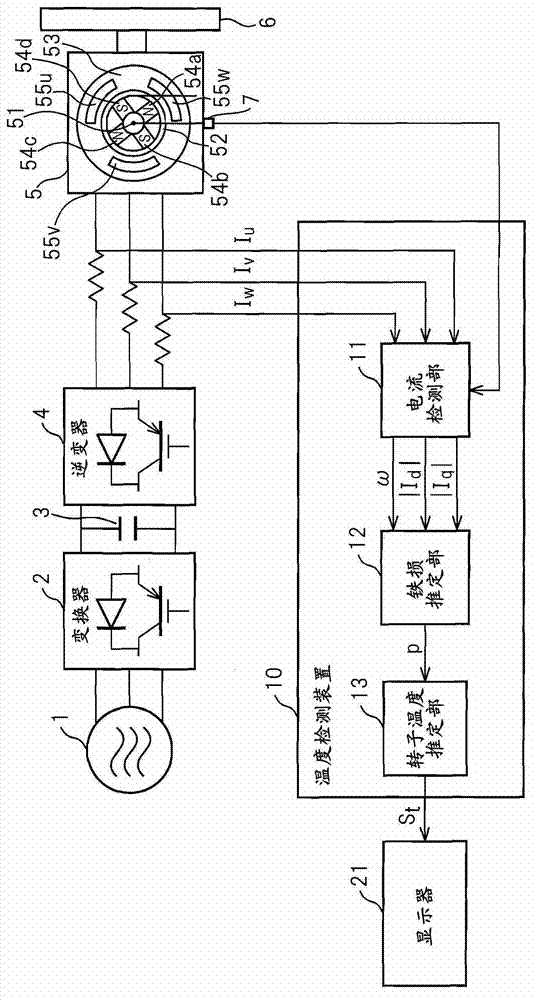
[0040] With reference to the accompanying drawings, figure 1 It is a block diagram of a system including the temperature detection device according to the first embodiment of the present invention. figure 1 The system shown has a three-phase AC power supply 1 , a converter 2 , a filter capacitor 3 , an inverter 4 , a permanent magnet synchronous motor 5 , a driven body 6 , an encoder 7 , a temperature detection device 10 , and a display 21 .

[0041] The converter 2 is composed of, for example, a plurality (six in the case of three-phase AC) rectifier diodes and transistors connected in antiparallel to these rectifier diodes, and converts the AC power supplied from the three-phase AC power supply 1 into DC power. . The filter capacitor 3 is connected i...


PUM


Abstract

The invention provides a temperature detection device for detecting temperature of a rotor of a motor. The temperature detection device has a current detection unit configured to detect a current value of a current flowing through a winding with which any one of a stator and the rotor of the motor is provided, an iron loss estimation unit configured to estimate an iron loss of the rotor using the current value, and a rotor temperature estimation unit configured to estimate the temperature of the rotor using the iron loss.

Description

technical field [0001] The present invention relates to a temperature detection device for detecting the temperature of a rotor of a motor in order to protect the rotor of the motor from overheating. Background technique [0002] Conventionally, in a temperature detection device for protecting a motor having a stator and a rotor from overheating, the temperature of the coil is detected by a temperature detection element such as a thermistor or a thermostat installed near the stator coil. An alarm signal is generated in case a predetermined value is exceeded. [0003] In addition, for example, Japanese Patent Application Laid-Open No. 2009-261078 (JP2009-261078A) proposes to consider motor loss in addition to the temperature detected by the temperature detector when detecting the temperature of the coil to protect the motor from overheating. temperature detection device. [0004] However, the existing temperature detection device is used to protect the coil from overheating...

Claims


Application Information

Patent Timeline
Patent Type & Authority Applications(China)
IPC IPC(8): G01K13/00G01R19/00G01K1/14G01K7/00G01K13/08H02P21/00H02P21/14H02P21/18H02P21/22H02P21/24H02P21/28H02P23/00H02P23/14H02P27/08
CPCH02P21/00G01R19/00H02P29/0044H02P29/02G01K13/00H02P27/06G01K7/00G01R31/343H02P29/60
Inventor 妹尾达也
Owner FANUC LTD
Why Eureka
Try Eureka