Reactor temperature monitoring system

A monitoring system and reactor technology, used in thermometers, thermometer parts, instruments, etc., can solve the problems of strong electric field, magnetic field and strong electromagnetic interference, large temperature monitoring error, large positioning error, etc., to achieve simple network structure, The effect of easy networking

Inactive Publication Date: 2016-12-21
ZHUHAI YADO MONITORING TECH CO LTD
View PDF3 Cites 2 Cited by
  • Summary
  • Abstract
  • Description
  • Claims
  • Application Information

AI Technical Summary

Problems solved by technology

Portable infrared temperature monitoring cannot detect the internal temperature, and the temperature monitoring error is relatively large, and remote real-time monitoring cannot be performed, so that the high temperature operation failure of the reactor cannot be found in time
The positioning error of the distributed optical fiber temperature monitoring method is very large, and the usual positioning accuracy is about 3 meters, which makes the temperature monitoring result inaccurate; the optical fiber grating temperature monitoring method requires a large number of grating sensors and optical fibers, and large-scale fixture accessories need to be customized for auxiliary fixing Installation, high cost, difficult to maintain
Because the reactor has a state of high voltage, strong magnetic field, high temperature, and high current, especially at the moment of a system accident, there will be a strong electromagnetic transient process, which will cause strong electric field, magnetic field, and strong electromagnetic interference, so conventional temperature monitoring is adopted It is difficult for the device to monitor the temperature of the reactor

Method used


Image

  • Reactor temperature monitoring system
  • Reactor temperature monitoring system
  • Reactor temperature monitoring system

Examples


Embodiment Construction

[0020] Below, in conjunction with accompanying drawing and specific embodiment, the present invention is further described:

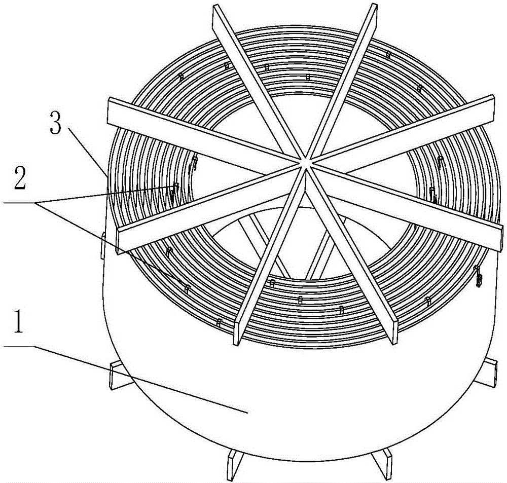
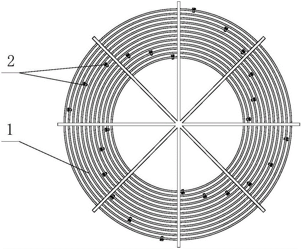
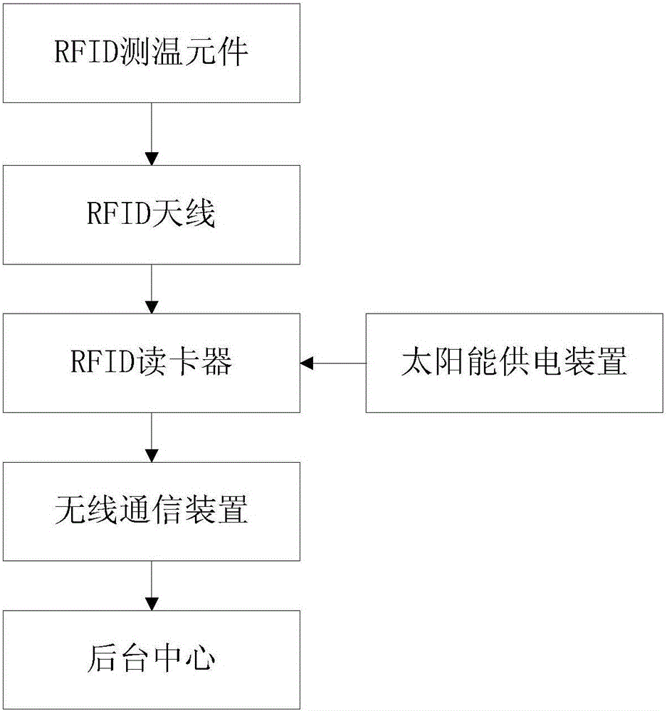
[0021] see Figure 1 to Figure 3 The present invention provides a reactor temperature monitoring system, including a reactor 1, several RFID temperature measuring elements 2, an RFID antenna, an RFID card reader, a solar power supply device, a wireless communication device and a background center. Among them, the RFID temperature measuring element 2 is wirelessly connected to the RFID card reader through an RFID antenna, the RFID card reader is wirelessly connected to the background center through a wireless communication device, and the solar power supply device supplies power to the RFID card reader; the reactor 1 has at least one layer of coils , the periphery of each layer of coils is covered with an encapsulation layer 3; the RFID temperature measuring elements 2 are installed on the top of the encapsulation layer 3, and the encapsulation layer 3 o...


PUM


Abstract

The invention discloses a reactor temperature monitoring system, and the system comprises a reactor which is provided with at least one coil layer. The periphery of each coil layer is coated with a packaging layer. The system also comprises a plurality of RFID temperature measuring elements, an RFID antenna, an RFID card reader, a solar energy supply device, a wireless communication device, and a background center. The RFID temperature measuring elements are in wireless communication with the RFID card reader through the RFID antenna. The RFID card reader is in wireless communication with the background center through the wireless communication device. The RFID temperature measuring elements are respectively disposed at the top of the packaging layer, and the packaging layer of each coil layer correspondingly comprises two RFID temperature measuring elements. The system carries out the distributed temperature detection of an reactor, and more effectively detects the temperature of coils. Moreover, the power of the RFID temperature measuring elements is supplied from the outside in a wireless manner. The system employs wireless communication, is enabled to be simple and clear in network structure, and is easy for networking.

Description

technical field [0001] The invention relates to the technical field of temperature detection, in particular to a reactor temperature monitoring system. Background technique [0002] The reactor is used in the power system to limit the current impact caused by the sudden change of the grid voltage and the operating overvoltage, smooth the power supply voltage, and improve the power factor. Power Quality. Therefore, it is widely used in the field of power system. Under the action of high temperature, electric field and magnetic field for a long time, the insulating material in the reactor will gradually lose its original mechanical properties and insulating properties, such as brittleness, weakening of mechanical strength, and electrical breakdown. [0003] The reactor is composed of winding coils, terminals and some accessories. It is mainly cooled by natural air. Except for the relay protection characterized by current, there is no gas monitoring and protection measures, a...

Claims


Application Information

Patent Timeline
IPC IPC(8): G01K1/02G01K1/14G06K17/00G01K1/024
CPCG06K17/0022G01K1/024G01K1/14
Inventor 田斌郭晨华杨志强
Owner ZHUHAI YADO MONITORING TECH CO LTD
Why Eureka
Try Eureka