Intercardiac defibrillation catheter system

A technology of probes and heart chambers, applied in the field of probe systems, which can solve the problems of defibrillation probes not being able to move and not being stored

Active Publication Date: 2013-01-30
JAPAN LIFELINE CO LTD
View PDF5 Cites 5 Cited by
  • Summary
  • Abstract
  • Description
  • Claims
  • Application Information

AI Technical Summary

Problems solved by technology

[0015] However, in such a control method, when the power supply unit is removed from the defibrillation probe, the time of connection is cleared, and by reconnecting the power supply unit, the time of reconnection becomes the starting point of the usage limit time, and it is possible to Start and move using time limit
[0016] In this case, it is also conceivable to assign a serial number that can be read by the power supply unit to the defibrillation probe, so that the power supply unit connected to the defibrillation probe stores the serial number. When the needle is reconnected, the time when the defibrillation probe is first connected is used as the starting point, and after the usage limit time has elapsed from this time, the defibrillation probe is controlled so that the defibrillation probe cannot be operated.
[0017] However, in such a control method, when not one power supply unit is connected to the defibrillation probe, for example, when a spare power supply unit is reconnected in the process, the defibrillation probe will be disabled in the reconnected power supply unit. The history information of the operation of the probe using the power supply unit connected first (the time when the power supply unit was first connected) is not stored, so the time of reconnection becomes the starting point, and it may be activated again from this time.

Method used


Image

  • Intercardiac defibrillation catheter system
  • Intercardiac defibrillation catheter system
  • Intercardiac defibrillation catheter system

Examples


no. 1 Embodiment approach >

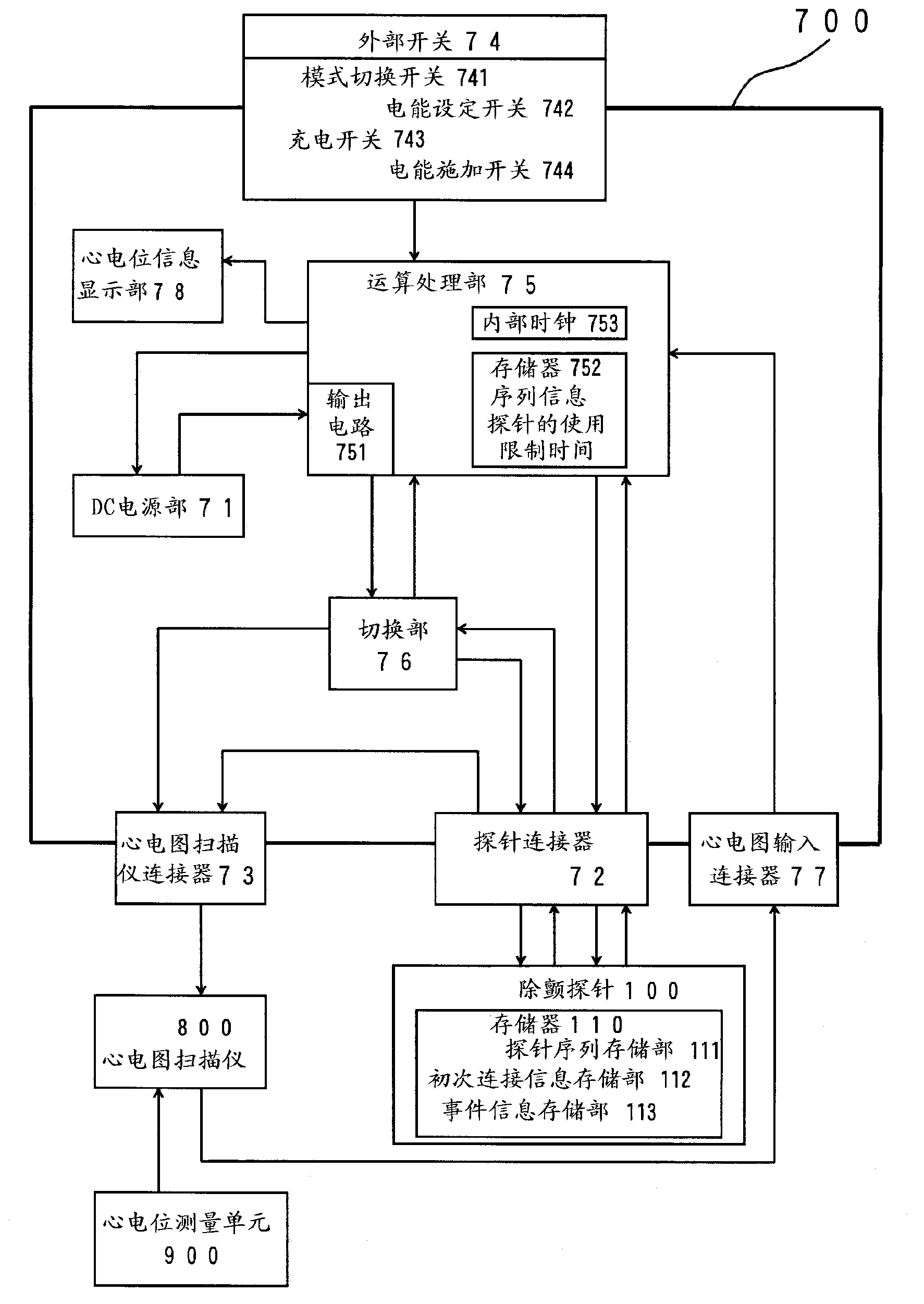
[0119] The intracardiac defibrillation probe system according to this embodiment includes: a defibrillation probe 100 inserted into a cardiac cavity for defibrillation, a power supply device 700 for applying a DC voltage to electrodes of the defibrillation probe 100 , and an electrocardiogram scanner. 800, and a cardiac potential measurement unit 900.

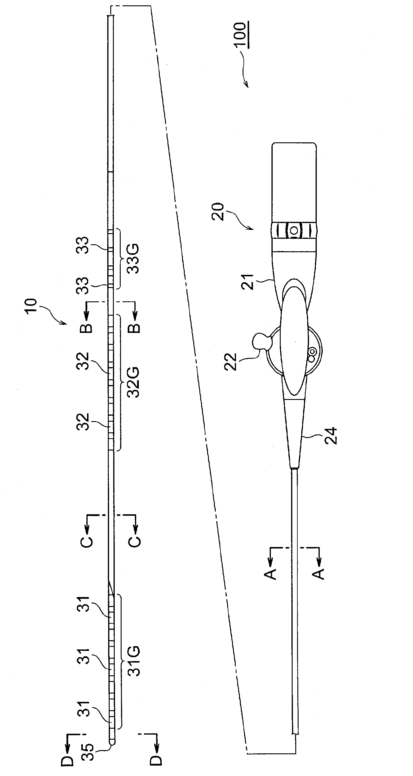
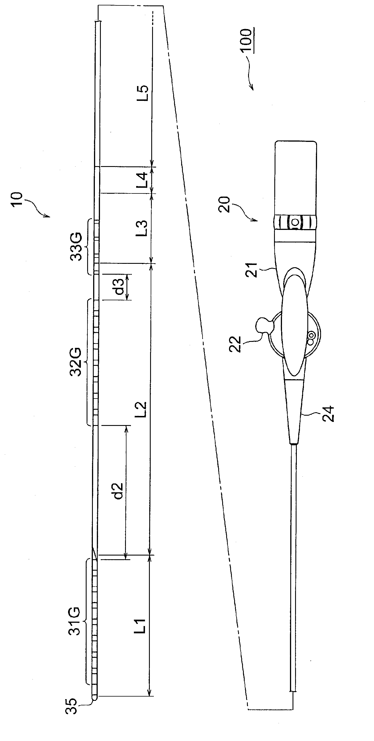
[0120] The defibrillation probe 100 has: a multi-lumen tube 10;

[0121] A first DC electrode group 31G composed of eight ring-shaped electrodes 31 mounted on the top region of the multi-lumen tube 10;

[0122] A second DC electrode group 32G composed of eight ring-shaped electrodes 32 attached to the multi-lumen tube 10 away from the first DC electrode group 31G toward the base end;

[0123] A proximal side potential measuring electrode group 33G composed of four annular electrodes 33 attached to the multi-lumen tube 10 away from the second DC electrode group 32G toward the proximal side;

[0124] A first wire group 41G comp...

no. 2 Embodiment approach >

[0363] Figure 18 It is a block diagram showing another embodiment of the intracardiac defibrillation probe system of the present invention. In this figure, the same symbols are used for the same or corresponding components as those of the first embodiment.

[0364] The arithmetic processing unit 75a of the power supply device 700a constituting the probe system according to this embodiment determines whether the defibrillation probe 100 is to execute a new event (for example, defibrillation) from the memory 110 written in the defibrillation probe 100. Whether the elapsed time from the time when the information storage unit 112 is connected for the first time to the current time indicated by the internal clock 753 exceeds the usage limit time stored in the memory 752 of the power supply device 700a, if it is judged to be exceeded, the event is controlled so as not to be executed.

[0365] Figure 19 is a representation of Figure 18 A flowchart of the operation and operation o...


PUM


Abstract

Disclosed is an intercardiac defibrillation catheter system provided with a defibrillation catheter (100) and a power source device (700); wherein the defibrillation catheter (100) is provided with a memory (110) comprising an initial connection information storage unit (112) and an event information storage unit (113); and the power source device (700) is provided with an arithmetic processing unit (75) which comprises an output circuit (751) of direct current voltage, a memory (752) for storing a usage time limit, and an internal clock (753), and which controls writing to and reading from the memory (110) of the defibrillation catheter (100). The arithmetic processing unit (75), for each event that has been written to the event storage unit (113) of the memory (110) of the defibrillation catheter (100), performs control so that the next event is not executed if the elapsed time between the connection time that has been written to the initial connection information storage unit (112) of the memory (110) of the defibrillation catheter (100) and the time that the first-mentioned event has been performed has been determined to exceed the usage time limit.

Description

technical field [0001] The present invention relates to an intracardiac defibrillation probe system, and specifically relates to a probe system including a defibrillation probe inserted into a cardiac cavity and a power supply device for applying a DC voltage to electrodes of the defibrillation probe. Background technique [0002] An external defibrillator (AED) is known as a defibrillator for eliminating ventricular fibrillation (for example, refer to Patent Document 1). [0003] In AED-based defibrillation therapy, electric energy is supplied to the patient's body by applying a DC voltage by attaching electrode pads to the patient's body surface. Here, the electric energy flowing from the electrode pads into the patient's body is usually 150 to 200 J, and part of it (usually about several to 20%) flows to the heart for defibrillation treatment. [0004] Patent Document 1: Refer to Japanese Patent Application Laid-Open No. 2001-112874 [0005] In addition, ventricular fib...

Claims


Application Information

Patent Timeline
Patent Type & Authority Applications(China)
IPC IPC(8): A61N1/39
CPCA61N1/3956A61N1/0563A61N1/39A61N1/20A61N1/378A61N1/3968A61N1/3975A61B5/287
Inventor 小野寺泰
Owner JAPAN LIFELINE CO LTD
Why Eureka
Try Eureka