Hybrid 2-level and multilevel HVDC converter

A technology of high-voltage direct current and voltage source converters, which can be applied in the direction of reducing harmonics/ripples in DC circuits, converting AC power input to DC power output, and power transmission AC networks. It can solve the problem of increasing the size, weight and Cost and other issues, to achieve the effect of minimizing DC ripple, minimizing harmonic distortion, and reducing installation costs

Active Publication Date: 2013-01-30
ALSTOM TECH LTD
View PDF2 Cites 18 Cited by
  • Summary
  • Abstract
  • Description
  • Claims
  • Application Information

AI Technical Summary

Problems solved by technology

However, the high voltage nature of power transmission means that larger passive inductive and capacitive components must be employed, which increases the size, weight and cost of the associated power station

Method used


Image

  • Hybrid 2-level and multilevel HVDC converter
  • Hybrid 2-level and multilevel HVDC converter
  • Hybrid 2-level and multilevel HVDC converter

Examples


Embodiment Construction

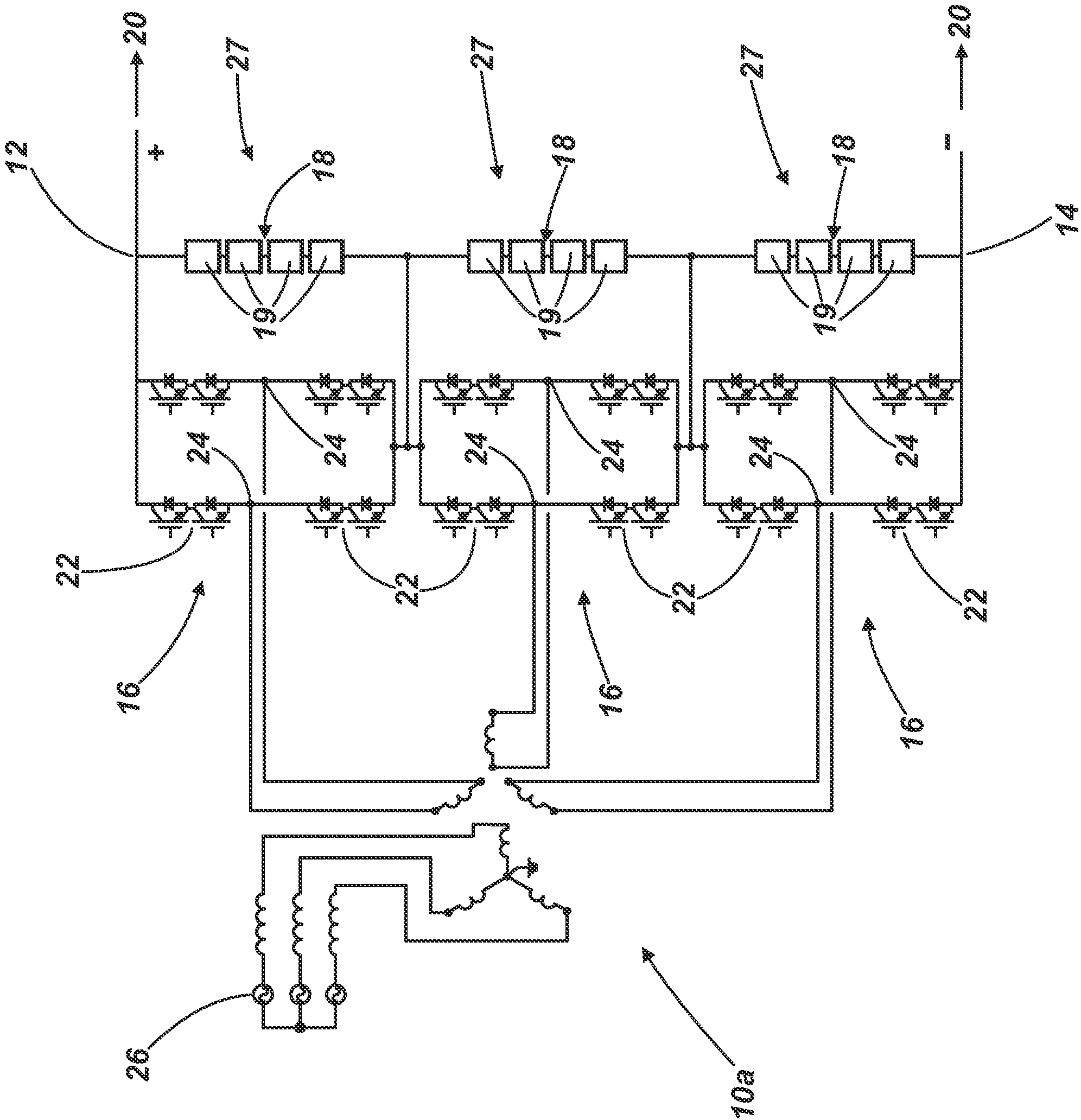
[0050] figure 1 A voltage source converter 10a according to a first embodiment of the present invention is shown in .

[0051] The voltage source converter 10 a comprises first and second DC terminals 12 , 14 , three phase elements 16 and three auxiliary converters 18 .

[0052] In use, the first and second DC terminals 12, 14 are respectively connected to positive and negative terminals of the DC network 20, which respectively carry +V DC / 2 and -V DC / 2 voltage, where V DC is the voltage range of the DC network 20 .

[0053] Each phase element 16 includes two pairs of series primary switching elements 22 connected in parallel. Each primary switching element 22 is in the form of one or more IGBTs connected in series, each IGBT connected in parallel with an anti-parallel diode. The midpoints of each string of switching elements 22 in series define AC terminals 24 for connection in use to respective phases of a three-phase AC network 26 .

[0054] In use, the primary swit...


PUM


Abstract

A voltage source converter (10a) is used in high voltage direct current power transmission and reactive power compensation. The voltage source converter (10a) comprises first and second DC terminals (12, 14) for connection in use to a DC network (20), three phase elements (16) and at least one auxiliary converter (18) connected between the first and second DC terminals (12, 14), each phase element (16) including a plurality of primary switching elements (22) and at least one AC terminal (24) for connection in use to a respective phase of a multiphase AC network (26), the plurality of primary switching elements (22) being controllable in use to facilitate power conversion between the AC and DC networks (26, 20), the or each auxiliary converter (18) being operable in use to act as a waveform synthesizer to modify a first DC voltage presented to the DC network (20); so as to minimise ripple in the DC voltage.

Description

technical field [0001] The present invention relates to a voltage source converter for use in high voltage direct current (HVDC) power transmission and reactive power compensation and a method of operating a voltage source converter. Background technique [0002] In power transmission networks, alternating current (AC) power is typically converted to direct current (DC) power for transmission over overhead lines and / or submarine cables. Through this conversion, there is no need to compensate for the effect of AC capacitive loading imposed by these lines and / or cables, thereby reducing the cost per kilometer of these lines and / or cables. Therefore, the conversion from AC to DC becomes cost-effective when power needs to be transmitted over long distances. [0003] Conversion of AC to DC power is also used in power transmission networks where it is necessary to interconnect AC networks operating at different frequencies. In any such power transmission network, a converter is ...

Claims


Application Information

Patent Timeline
Patent Type & Authority Applications(China)
IPC IPC(8): H02M7/797H02M1/15H02M1/12H02J3/36
CPCH02M1/12H02M1/15H02M7/797Y02E60/60H02J3/01H02J3/36H02M2007/4835Y02E40/40H02M7/483H02M7/4835H02M1/0095H02H7/1213H02H7/1255H02J3/18
Inventor 乔纳森·查尔斯·克莱尔马泰奥·托马西尼戴维·特雷纳罗伯特·怀特豪斯
Owner ALSTOM TECH LTD
Why Eureka
Try Eureka