
Accumulation type trolley conveyor impulse sender

A technology of hanging conveyor and numbering device, which is applied to conveyor objects, conveyor control devices, transportation and packaging, etc., can solve the problems of high cost, difficult popularization and application, complex structure, etc., and achieves simple production and reduced production process. , the effect of convenient installation

Inactive Publication Date: 2013-02-06
HUBEI HUACHANGDA INTELLIGENT EQUIP
View PDF8 Cites 3 Cited by
  • Summary
  • Abstract
  • Description
  • Claims
  • Application Information

AI Technical Summary

Problems solved by technology

The structure of the generator in this patent adopts a non-contact signal trigger method, which can prevent the components of the generator from falling off and facilitate displacement, but there are problems of complex structure and high cost, so it is difficult to popularize and apply in practice

Method used


Image

  • Accumulation type trolley conveyor impulse sender
  • Accumulation type trolley conveyor impulse sender
  • Accumulation type trolley conveyor impulse sender

Examples


Embodiment 1

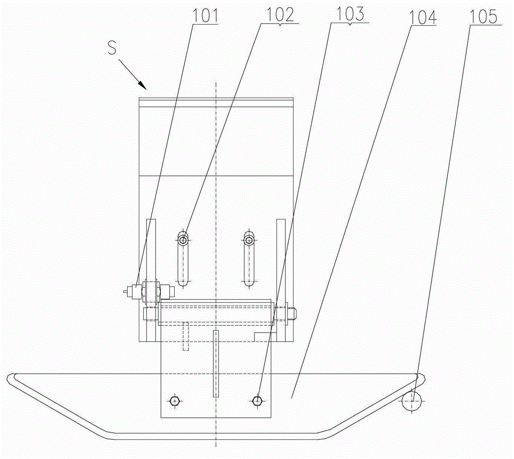
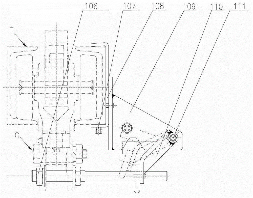
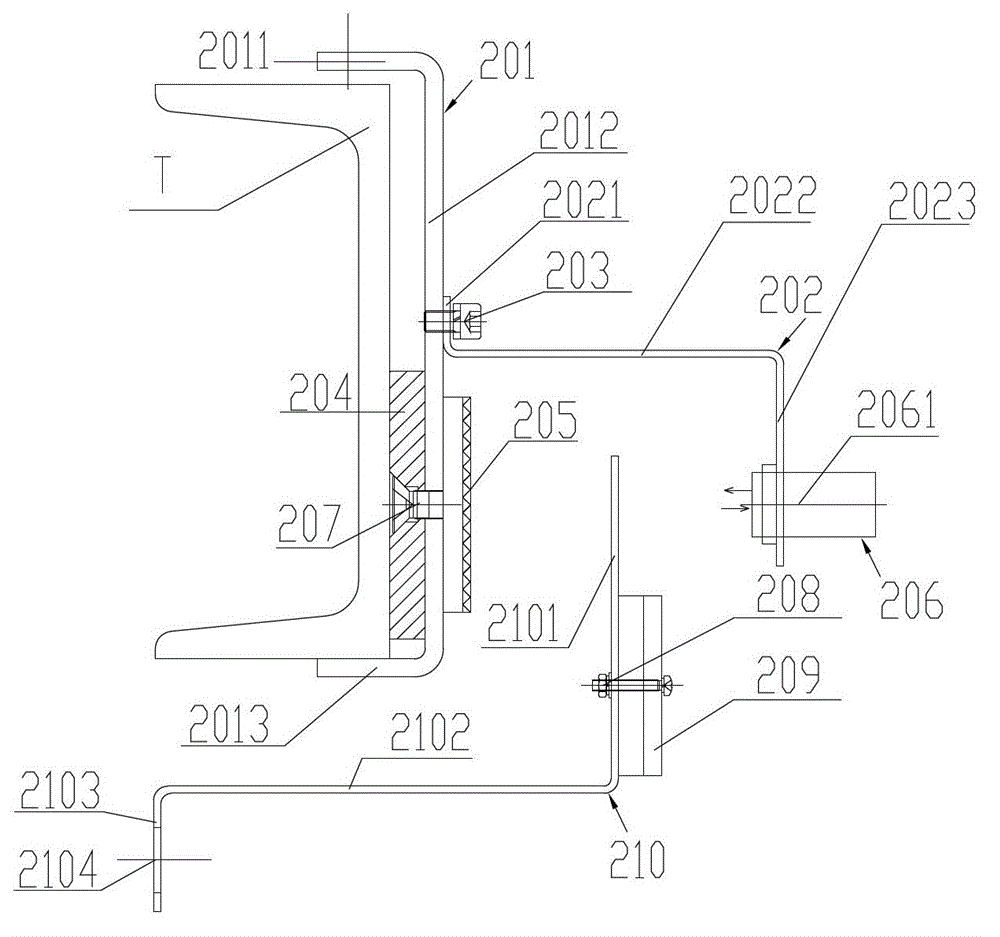
[0025] see Figure 2a , Figure 2b , represents the mechanical principle structure of a preferred embodiment of the signal generator of the accumulation type suspension conveyor of the present invention. This embodiment provides a kind of manufacturing simple, reliable in use, easy to adjust the positive and negative accumulative type suspension conveyer number issuer, it comprises photoelectric switch 206 and issue plate 210: photoelectric switch 206 is installed on the carrying track T, issue plate 210 installed in the cargo trolley ( Figure 2a , Figure 2b not shown), wherein the signaling board 210 can run into the transmitter-receiver optical path of the photoelectric switch 206, so as to trigger the photoelectric switch 206 to send a switching signal, which is transmitted to the In the logic control system PLC of the product-free suspension conveyor, the running route of the cargo trolley is finally determined by controlling the action of the switch tongue (not shown...

Embodiment 2

[0040] Different from Embodiment 1, this embodiment adopts other forms of photoelectric switches 206, such as through-beam photoelectric switches, diffuse reflection photoelectric switches, mirror emission photoelectric switches, optical fiber photoelectric switches, etc. It is sufficient to be able to cut into the optical path between the transmitter and the receiver.

[0041] For example, simply adopting the through-beam photoelectric switch 206 can well meet the requirements of the present invention. The emitter and the reflector of the through-beam photoelectric switch are structurally separated from each other, and the two are relatively arranged. Correspondingly, the reflector 205 is omitted. When the signaling board 210 cuts between the transmitter and the receiver, it blocks the optical paths of the two and causes the state of the photoelectric switch 206 to change, thereby triggering the detection circuit of the photoelectric switch 206 to send a switching signal.


PUM


Abstract

The invention relates to the field of conveying equipment and discloses an accumulation type trolley conveyor impulse sender. The accumulation type trolley conveyor impulse sender comprises a photoelectric switch installed on a load bearing rail and an impulse sending plate installed on a cargo buggy, wherein the impulse sending plate can operate to an emitter-receiver light path of the photoelectric switch so as to trigger the photoelectric switch to send a switch signal. The accumulation type trolley conveyor impulse sender disclosed by the invention utilizes the structural form of combining the photoelectric switch with the impulse sending plate, so that the accumulation type trolley conveyor impulse sender is convenient and firm to install, and a signal can be triggered without touching or colliding the photoelectric switch with the impulse sending plate, so that the failure rate of the impulse sender can be effectively reduced.

Description

technical field [0001] The invention relates to the field of conveying equipment, in particular to a power-and-free suspension conveyor signal generator, which adopts a non-contact trigger signal form, which is convenient for installation and maintenance, and can also reduce mechanical failures. Background technique [0002] The power&free overhead conveyor is a flexible and highly automated advanced conveying equipment. It can not only undertake simple material handling functions, but also solve complex material storage and transportation problems. Therefore, it is widely used in modern large play an increasingly important role in production. In a typical accumulative suspension conveyor, the trolley is supported on the load rail, pushed by the push rod on the traction part, the stop of the trolley is controlled by the stopper, and the trolley runs along different routes by the switch . Specifically, a signaler is installed on the turnout, and a signaler is set on the tro...

Claims


Application Information

Patent Timeline
IPC IPC(8): B65G43/00
Inventor 单显余
Owner HUBEI HUACHANGDA INTELLIGENT EQUIP
Features
  • Generate Ideas
  • Intellectual Property
  • Life Sciences
  • Materials
  • Tech Scout
  • Unparalleled Data Quality
  • Higher Quality Content
  • 60% Fewer Hallucinations
Learn More