Backlight module and liquid crystal display device

A backlight module and light coupling technology, which is applied in the direction of lighting devices, fixed lighting devices, lighting device components, etc., can solve the problems of easy deformation, low bonding strength, and affecting electrical performance, etc., so as to achieve non-deformation and high strength Effect

Active Publication Date: 2013-02-06
SHENZHEN CHINA STAR OPTOELECTRONICS TECH CO LTD
View PDF9 Cites 9 Cited by
  • Summary
  • Abstract
  • Description
  • Claims
  • Application Information

AI Technical Summary

Problems solved by technology

The distance between the light emitting surface of the light bar and the light incident surface of the light guide plate is called the light coupling distance, which is an important optical parameter. When the light coupling distance changes, the optical performance of the backlight module will change accordingly. In order to improve the backlight The optical taste of the module needs to strictly control the coupling distance, such as figure 1 As shown, the method adopted in the prior art is to set a metal block 4 on the light bar 1, the metal block 4 is in contact with the light incident surface of the light guide plate 3, and the thickness of the metal block 4 is designed to control the light bar 1 and the light guide plate 3 The light coupling distance between them, but because the metal block is fixed on the light strip by patch technology, the bonding strength is low, and it is often not firm, and it is easy to fall off when the backlight module is impacted by external force, thus losing the effect of controlling the light coupling distance ; In addition, the light bar is an electronic part, and when it is used as a structural part, it is easy to deform, which will affect the electrical performance

Method used


Image

  • Backlight module and liquid crystal display device
  • Backlight module and liquid crystal display device
  • Backlight module and liquid crystal display device

Examples


Embodiment Construction

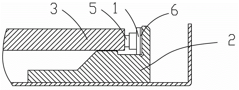
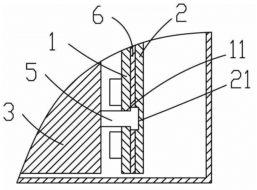
[0023] The present invention discloses a liquid crystal display device, including a backlight module, as Embodiment 1 of the backlight module of the present invention, such as Figures 2 to 4 As shown, the backlight module includes a light bar 1, a light bar heat sink 2 and a light guide plate 3. There is a light coupling distance between the light bar 1 and the light guide plate 3. The backlight module also includes a The distance control part 5, the light bar 1 is provided with a through hole 11, the control part 5 passes through the through hole 11, the control part 5 is arranged on the light bar heat sink 2, and the light bar heat sink 2 2 providing a fixing force for controlling the position of the light guide plate 3 .

[0024] In this embodiment, the control member 5 includes a body 51 and a root portion 52, the cross section of the root portion 52 is larger than the cross section of the body 51, and the root portion 52 is clamped between the light bar 1 and the heat si...


PUM


Abstract

The invention belongs to the field of liquid crystal display, and particularly relates to a liquid crystal display device and a backlight module. The backlight module includes a lamp strip, a light strip heat sink and a light guide plate, wherein an opto-coupling distance is arranged between the lamp strip and the light guide plate; and the backlight module further includes a controller used for controlling the opto-coupling distance, wherein a through hole is arranged in the lamp strip, the controller penetrates the through hole, the controller is arranged on the light strip heat sink, and the light strip heat sink provides the fixing force for controlling the position of the light guide plate. In the backlight module, the controller used for controlling the opto-coupling distance is not arranged on the lamp strip, but on the light strip heat sink, so that the fixing force for controlling the position of the light guide plate is not born by the lamp strip any longer, and is transferred onto the lamp strip heat sink; and the lamp strip is an aluminum extrusion profile with certain thickness and high strength, and can bear larger fixing force, therefore, the lamp strip is not influenced by external force any longer, is prevented from deformation easily, and avoids influence on electric properties.

Description

technical field [0001] The invention belongs to the field of liquid crystal display, and more specifically relates to a backlight module and a liquid crystal display device. Background technique [0002] In the prior art, a liquid crystal display device generally includes a liquid crystal display panel and a backlight module. Since the liquid crystal display panel cannot emit light, the backlight module needs to provide a surface light source that emits uniform light. The light source of the side-light backlight module is generally a light bar. Since the light bar generates high heat, it is necessary to provide a light bar heat sink to improve heat dissipation efficiency. The distance between the light emitting surface of the light bar and the light incident surface of the light guide plate is called the light coupling distance, which is an important optical parameter. When the light coupling distance changes, the optical performance of the backlight module will change accor...

Claims


Application Information

Patent Timeline
Patent Type & Authority Applications(China)
IPC IPC(8): F21S8/00F21V17/10F21V15/00G02F1/13357
CPCF21V15/00G02B6/001F21V17/10F21S8/00G02B6/0091G02B6/0085
Inventor 李全
Owner SHENZHEN CHINA STAR OPTOELECTRONICS TECH CO LTD
Why Eureka
Try Eureka